| Vocademy |
Phonograph Players
Please note that this chapter is in outline form and will be fleshed out later. Use it to guide you through your own research.
Many people prefer the sound of vinyl recording
Digital recording more faithfully reproduces the dynamic range of the original performance. However, the dynamic range of vinyl recording is significantly limited compared to human hearing. Therefore, loud sounds must be made quieter, and soft sounds must be made louder before recording (dynamic range compression).
To reduce the sound of clicks and pops caused by the stylus riding over scratches or debris, high frequencies are reduced in volume on playback. High frequencies are emphasized during recording to compensate for the resulting loss in high-frequency definition. This is called RIAA emphasis and equalization.[1]
Phonograph recording techniques
Note: With a few exceptions, each side of a vinyl recording has a single sprial groove.[2] Referring to the adjacent courses of this groove as "grooves" is therefore technically incorrect. However, as is the standard in the recording industry, the adjacent courses of the single spiral groove will collectively be called "grooves" in this discussion.
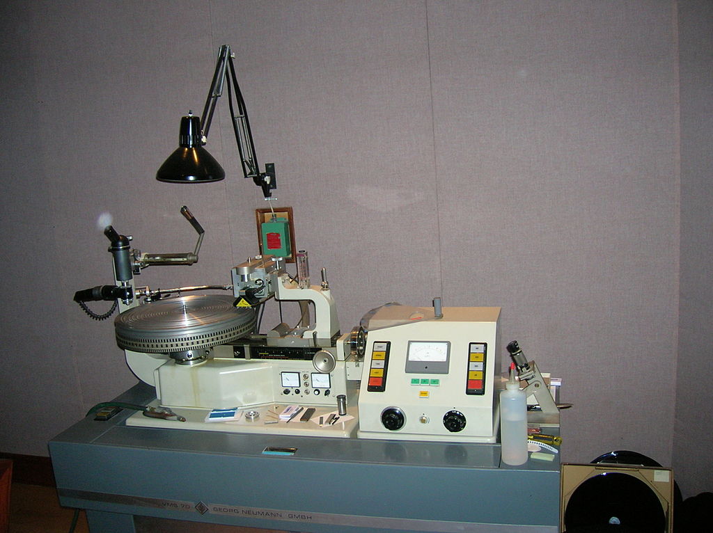
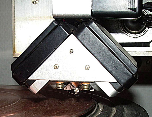
A vinyl record is created by first cutting a master on a record cutting lathe.
 |
|
|
 |
|
|
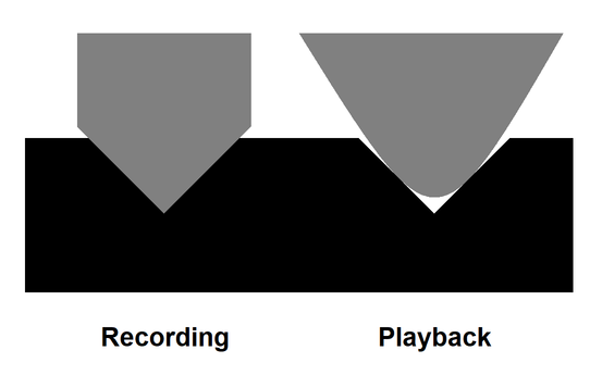
The cutting stylus or blade has a sharp edge to facilitate cutting the groove into the master materia.
 |
|
|
Originally, masters were cut into wax but modern equipment uses spin-coated lacquer on aluminum.
Once the record is cut into the lacquer, the master is carefully cleaned and inspected. Some flaws may be cleaned by hand using a microscope and appropriate tools. The lacquer master is then dipped into a stannous chloride solution. After washing with water, a thin layer of stannous chloride remains on the lacquer.
Next, the master is sprayed with silver nitrate, which cures (catalyzed by the stannous chloride) into a silver coating. After washing, the disk is electroplated with copper or nickel. Once this first fine coating is laid down, a coarser coating can be applied in a few hours. Once the metal is thick enough to support itself, it is removed from the master.
This metal "negative" could be used to stamp records out of hot vinyl, but instead, it is used to create a "Mother." First, the silver is chemically stripped from the metal negative because the silver will quickly oxidize. Next, a conductive mold-release chemical is applied to the negative surface, and a new layer of copper or nickel is electroplated into it. Then, a course layer is again built upon the negative until it is thick enough to be self-supporting. The mold release layer facilitates separating this Mother from the negative.
|
Finally, the same process is used to create multiple stampers from the Mother. These stampers are plated with a chromium alloy to reduce wear during the stamping process.
Two stampers are attached to the record press (one for each side of the record) and are heated to the proper temperature. A technician places a label, a soft blob of hot vinyl called a biscuit, and another label into the machine. Once loaded, the machine closes, forcing the biscuit into a vinyl-recorded disc. Water is circulated through cavities in the stamper to cool it and the record. Once cooled to the point where the record is rigid, it is removed. The stamping machine then reheats to repeat the process.
Problems
Linear tracking on cutting and pivoting tracking on playback
Groove distortions from the stylus diamater
Slower linear speed near the center of the platter compared to the edge
An LP record rotates at 33-1/3 RPM
Groove spacing changes with the loudness of the recording
Physical distortion of the lacquer while cutting causes some sound to leak into adjacent grooves.
Single and multichannel recording
Monaural
The groove makes a sinuous path that corresponds to the sound waves recorded on the disc.
Stereo
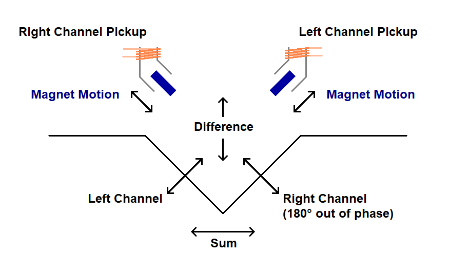
Each wall of the groove carries a separate channel. The walls are angled ±45º to the disc surface thus forming an angle of 90º to each other so that the movement along one wall is easily separated from movement along the other. Outer wall: right channel; Inner wall: left channel.
There is an intrinsic problem with this method of stereo recording. A sound that is equall in both channels will cause the stylus to move directly up and down. Loud sounds can throw the stylus upward so violently that it can lift off the record between wave peaks, causing severe distortion and possibly damaging the record. To mitigate this, one channel is fed with a signal that is 180 degrees out of phase. This causes the groove to move the stylus horizontally when the original signal is equal in the both channels. This would cause the two chanels to be out of phase except the pickup cartridge is wired with the channels 180 degrees out of phase, returning the signal to its normal phasing.[3] There is no standard for which channel is recorded 180 degrees out of phase. If the left channel is flipped during recording and the right channel is flipped during playback, the accoustic result is the same as if the left channel is flipped during playback.
Myth (sort of):
Several websites (and ChatGPT) claim a stereo recording is made by mixing the channels such that lateral motion represents the sum of the left and right channels and vertical motion represents the difference between the channels. This would make lateral motion the same as mixing the left and right channels into a single monoaural channel and using that to create horizontal motion of the groove. Extracting the left and right channels from these sum and difference signals to recreate the stereo signal would be trivial. This would theoretically make a single record compatible with both monaural and stereo systems.
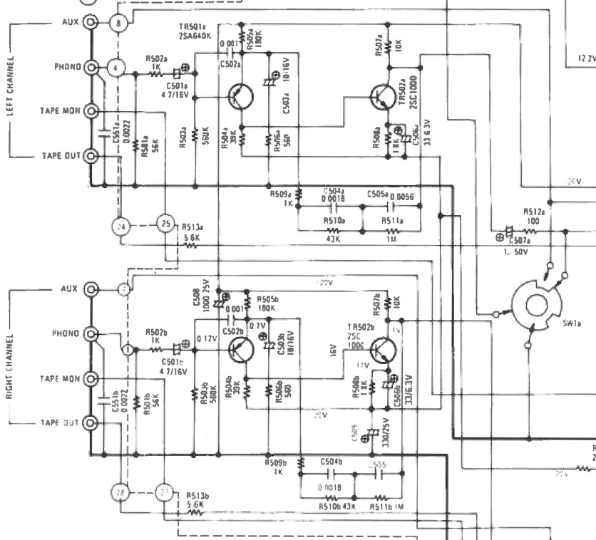
This is partially true because flipping the polarity of one channel when recording does precisely that; the horizontal motion contains the sum of the left and right channels, and the vertical motion contains the difference between the channels. Without flipping one channel, the vertical motion contains the sum, and the horizontal motion contains the difference. Flipping one channel on playback returns the signal to its normal orientation. If a player had a pickup sensitive to vertical and horizontal motion, the original stereo signal could easily be extracted with simple circuitry. However, the stereo information is contained in motion angled 45 degrees to the record surface, which is what the pickup is sensitive to. One transducer in the pickup extracts the signal from the outer wall of the groove, which is the right channel signal, and the other transducer extracts the signal from the inner wall of the groove, which is the left channel signal. The transducers are wired such that one channel has its phase inverted (it doesn't matter which one). This returns the left and right channels to their normal phasing; the signals presented by the pickup are in phase. The signal coming from the pickup consists of two shielded cables. One containing the left channel signal and the other containing the right channel signal. The fact that horizontal and vertical motion contain the sum and difference information is merely an artifact of the geometry of the recording; it is not an engineering decision. Nothing is being encoded or decoded. If you examinine the schematic of a typical stereo amplifier you will see the RIAA equalization filters and the preamps for the phono inputs but no circuitry to recover a stereo signal from a sum and difference signal.
 |
|
|
Furthermore, this does not make a stereo record fully compatible with a monoaural player. A monoaural record should only have horizontal motion in the groove. A stereo record has both horizontal and vertical motion in the groove. Playing a stereo recording on a monoaural player will produce a useful result. However, the vertical motion in the groove will cause sound artifacts and may cause the stylus to damage the recording. Monoaural players also tend to have a larger stylus than a stereo player, causing problems with the stylus tracking the groove.
 |
|
|
Three and four-channel recording
Matrix
The simplest matrix technique mixes a third channel into the two stereo channels. The third channel is mixed into one of the stereo channels in phase and 180 degrees out of phase into the other channel. This causes the third channel to sound as if coming from a diffuse area extending between the stereo speakers. To decode the third channel, one of the main channels is mixed into the other 180 degrees out of phase. Doing so causes any signal that is equal between the left and right channels to be canceled out (they are mixed 180 degrees out of phase). This leaves only the third channel and some of the sounds that are unequal in the left and right channels. In other words, if a sound is recorded so that it is only heard by the left or right speaker, that sound will also be heard in the third channel. The closer a sound is to the center (heard equally in both speakers), the less it appears in the third channel.
The third channel is sent to one or two speakers behind the listener, enabling sounds to appear anywhere in a circle around the listener. System artifacts affect the location of a particular sound, so sounds in the third channel cannot be precisely located, but the overall effect is usually pleasing. Theoretically, the front-to-back separation is only 3dB, meaning it can't be heard. Nevertheless, the human auditory system processes the sound and produces a much better effect than theory predicts.
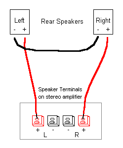
One advantage of this system is that the third channel can be decoded without any special circuitry. A third speaker or pair of speakers, wired in series, will decode the channel if the plus (red) input is connected to the plus of one channel and the minus (black) input is connected to the plus of the other channel. Neither minus (black) connector on the amplifier is connected.
 |
|
|
Improved systems such as SQ (Columbia) and QS (Sansui) used 90 degree phase shifts and weighted mixes to ehnance the third channel into left rear and right rear channels; four channels total. Front to rear separation was improved to as much as 20 dB. However, the artifacts introduced by this method tend to cause sounds to jump around. The overall effect is less than satisfactory.
Discrete
RCA developed a discrete four channel recording method that recorded four channels into a single groove. I cannot find a published specification on channel separation but I assume it is quite good.
Each wall of the groove carries audio frequencies for one channel and an ultrasonic carrier (like a radio carrier) that is amplitude modulated with a second channel. The audio frequency channel contains the sum of the front and rear channels. The channel on the ultrasonic carrier contains the difference (front channel minus rear channel). The decoder uses the difference information to extract the original front and rear channels from the audio frequency channel.
Phonograph reproduction
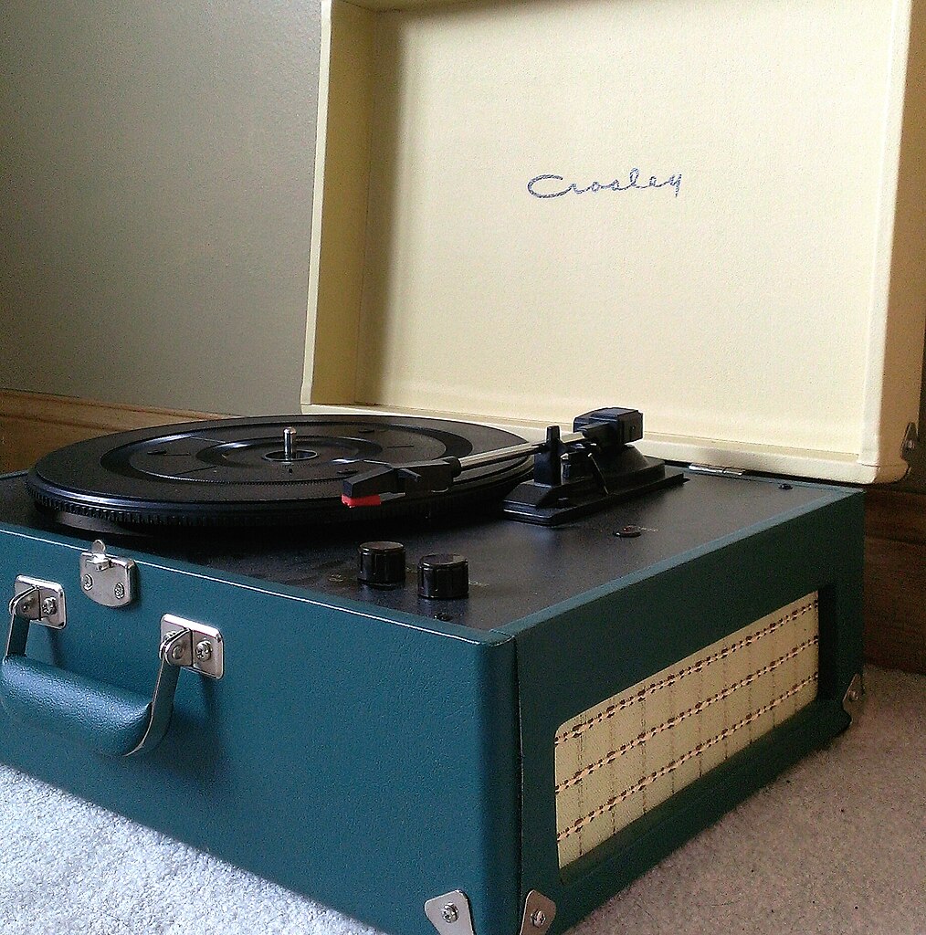
Some phonographs consist of an integrated turntable, amplifier and speakers. Most high quality phonographs consist of modular components with a separate turntable, amplifier and speakers.
,_around_1960.jpg) |
|
|
 |
|
|
.jpg) |
|
|
Turntable
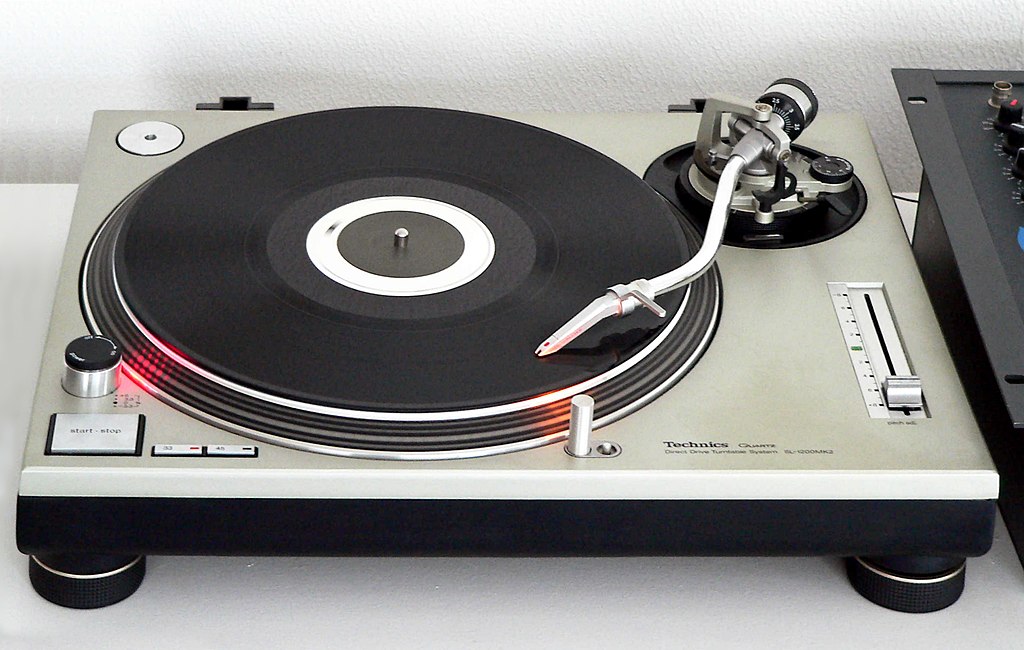
A turntable consists of a platter, a tone arm and a pickup (cartridge).
Geometry
The cutting lathe moves the cutting head along a lead screw. As the stylus moves side to side while cutting the groove, that movement is constantly perpendicular to the groove. It would be ideal to also track the playing stylus perpendicular to the groove. However, turntables, except linear-tracking turntables, have a tonearm that rotates on a pivot. This causes the head of the tonearm to move in an arc instead of a straight line as the cutting head does. The head cannot be perpendicular to the groove across the entire arc.
A simple solution to this would be to have the tonearm pivot located such that the head is tangent to the groove when the tonearm is halfway between the outer and inner grooves of the record. The tonearm would follow an arc as it tracked the groove. At the outer groove, a line drawn perpendicular to the groove where the groove intersects the arc would point to the left of the center of the record. Halfway through the playable part of the record, that line would intersect the center of the record, putting the head perpendicular to the groove. At the inner groove, that line would point to the right of the record's center. Note that the starting and ending points of the arc are both to the right of a line radial to the center of the record that intersects the middle of the arc.
However, the tonearm pivot is chosen so that the arc along which the head moves is rotated counterclockwise. This puts the arc's starting point to the right of a line radial to the center of the record and the arc's ending point to the left of that line. The tonearm head is canted to be generally correctly aligned with the groove. This geometry causes the head to move forward in the groove as it rotates with the tonearm. The result is that the stylus passes through two points where it is perfectly aligned with its transverse movement perpendicular to the groove. The stylus remains within about 1.5 degrees of perfect alignment throughout the arc.
|
Tonearm geometry The stylus tracks across the record in an arc shown in blue. |
||
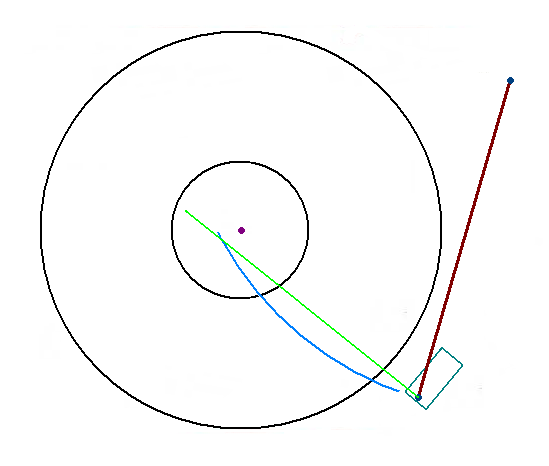 The tonearm is outside the record. The line perpendicular to the head (green) is considerably to the left of the record's center |
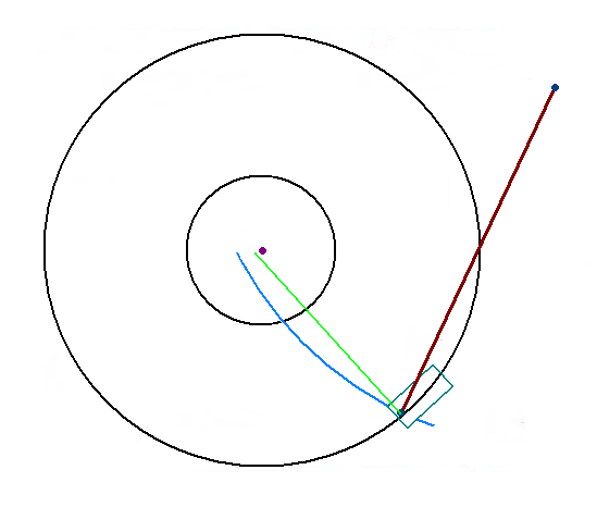 When the stylus is in the outer groove, the line perpendicualr to the head is about 1.5 degrees from the record's center |
|
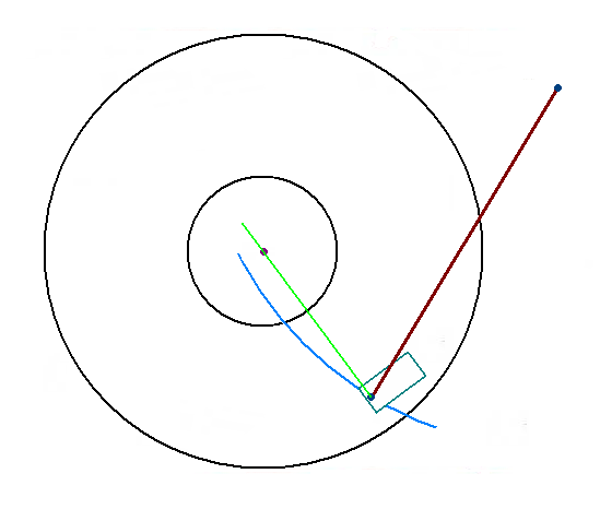 About 1/3 of the way through the record the head is perfectly aligned with the center of the record and the groove (at one of the two null points). |
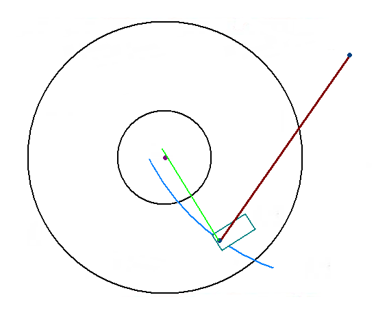 As the recrod plays the line perpendicular to the head moves to the right of the record's center. |
|
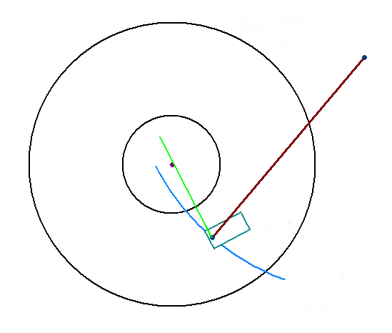 The line remains to the right of center through the middle third of the recording, staying within about one degree of perfect alignment. |
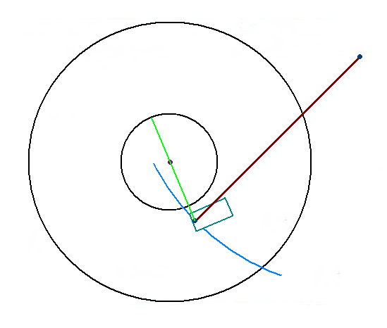 About 2/3 of the way throught the recording the head is again perfectly aligned with the center of the record and the groove (the second null point). |
|
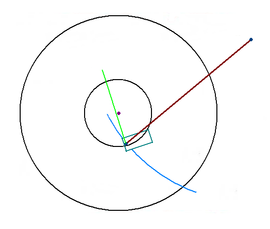 When the stylus reaches the inner groove the line perpendicular to the head has again moved to the left of the center of the record. |
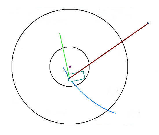 If the tonearm is moved beyond the inner groove, the line perpendicular to the head moves considerably to the left of the record's center. |
|
Counterweight
Antiskate
Pickup lever
Belt drive
direct drive
Idler drive
Must turn at 33-1/3 RPM for long-playing records
Must turn at 45 RPM for singles
45 RPM adapters
Record inserts
Turntable adapters
Single play and multiplay
Must not introduce vibrations to the record (they will be picked up by the stylus and heard in the speakers).
Some turntables have adjustable speed, others don't
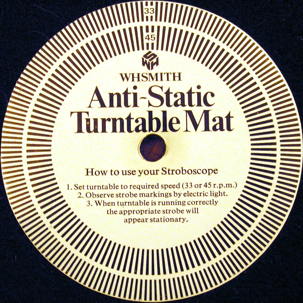
Some turntables have a speed indicator consisting of a ring with black and white stripes and a strobe light (usually no more than a neon light that naturally flashes at the line frequency). When present the strobe ring often appears through a window.. The system is designed such that the lines on the ring appear stationary when the turntable is turning at the correct speed. Strobe disks are available that can be placed on the turntable. These are intended to be viewed under fluorescent or LED light (connected to the mains/power grid). Such strobe disks may work under incandescent light, but some incandescent lights may not react to the line frequency fast enough to create the strobe effect. Such systems must be designed to work under 50 Hz or 60 Hz depending on the location where the equipment is used.
 |
|
|
 |
|
|
Tonearm
The tone arm is the arm that holds the pickup.
Tangent tracking
The simplest and most common tonearms are tangent tracking. The tonearm pivots near the edge of the record.
Linear tracking
|
Tonearm balancing
High quality pickup cartridges have light tracking forces. sets the proper weight/pressure of the stylus on the record. Hig
Anti-skate
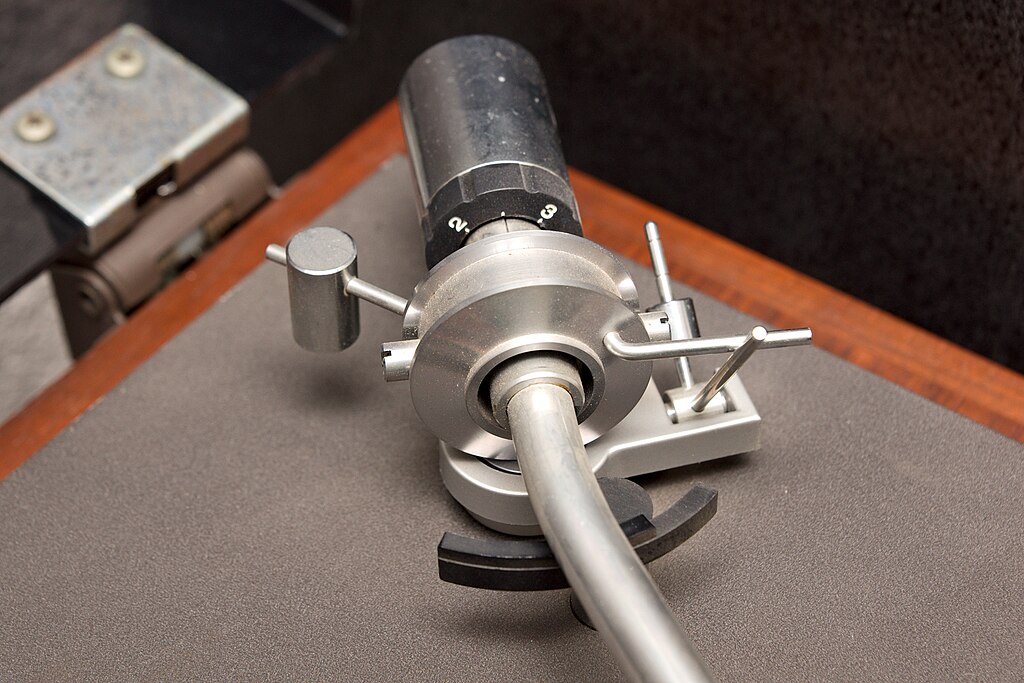
Looking at the geometry of the turntable, notice that the tonearm is not tangent to the groove but is angled toward the center of the record and, thus, the inner wall of the groove. Although the groove spirals toward the center of the record, carrying the stylus and tonearm with it, the geometry results in a net outward force on the tonearm. Unchecked by a heavy tonearm or anti-skate mechanism, this force would cause the tonearm to ride up the inner wall of the groove and stop tracking the groove. Many turntables mitigate this with an anti-skating mechanism that puts some outward force on the tonearm. There are multiple mechanisms to provide an anti-skate or bias force. Most consist of weight on a mechanism that converts the downward force of the weight to horizontal force on the tonearm.
 |
|
|
Styli
The stylus is the needle that contacts the record surface. These are usually made of diamond or sapphire, where diamond is the longer-lasting material. Styli also come in different shapes, some providing better performance.
Conical (spherical)
Cone shaped, spherical tip
Standard stylus shape
Inexpensive
Elliptical
Elongated transverse to the groove. The smaller radius of the edge allows the stylus to better track the smaller waveshapes of higher frequencies.
Shibata
Designed with a small-radius transverse to the groove to track the tiny curves of the ultrasonic frequencies on CD-4 disks.
Has a front/back profile with a larger contact area for less record wear.
For discrete 4-channel vinyl recordings from the 1970s
Other shapes
Several designs from the late 1980s onward that improve tracking and contact
Laser
Uses a laser to track the groove without physical contact
Pickup
Piezoelectric (crystal)
Efficient, does not require a preamp
Magnetic
Better frequency response
Requires preamp
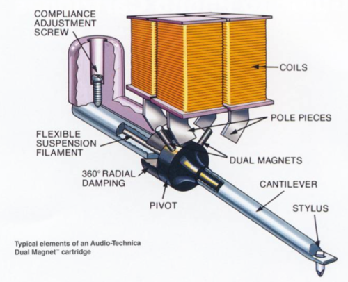
Magnetic pickups have a low voltage output and must be preamplified. Most amplifiers made from the 1960s on have sufficient preamplification built in.
Stereo pickups have two transducers, angled 90º to each other. Each transducer picks up vibrations from a different wall of the groove.
 |
|
|
Preamplification
RIAA Equalization
The equalization is in the amplifier. Connect the turntable to the Phono input. The sound from other inputs will be "tinny" because they don't apply the RIAA equalization.
Rotational speed
The rotational speed of the turntable is critical to reproducing sound with the correct pitch. Most turntables use synchronous motors that tie the rotational speed to the line or mains frequency. Therefore, a turntable has to be designed to operate in the region where it will be used. In North America and a few other areas, turntables operate with a line frequency of 60 Hz. Most of the world, they operate with a line frequency of 50 Hz.
Wow and flutter
Caused by eccentricity in pullies, drive wheels, etc.
Animaged electronmicrograph of needle in groove
https://youtu.be/GuCdsyCWmt8?si=SzJq3a307g6d7Hsa
—————————| Vocademy |