SURROUND SOUND
How it works
Build a passive matrix speaker network which decodes surround sound
Build a wireless surround sound system for as little as $40.00
WARNING!
The circuits and wiring diagrams below have been tested on several hi-fi
stereo systems with no damage to the systems. However, I cannot be responsible
for some hair-brained engineer who may have used a radical design that
might be damaged by an unorthodox speaker hookup. Use these circuits at
your own risk.
History of Surround Sound
After reading many articles about surround sound I have come to the
conclusion that most of the writers haven't done their homework. Some writers
trace the origin of surround sound to the 1976 movie Star Wars.
Others trace it to the abortive attempts at marketing quadraphonic (four-channel)
stereo in the early 1970's. Where did surround sound originate; what was
the first surround sound movie? So far, the earliest reference I have seen
to what is now called surround sound was a documentary on the making of
the 1940 Disney movie, Fantasia. The concept of encoding a third
channel into a stereo signal is so simple that I'm sure it was thought
of as soon as stereo sound was developed.
What about Star Wars? Star Wars was released in a six-channel
stereo format which was already at least 15 years old in 1976. I suspect
the truth is that, starting with Star Wars, surround sound became
almost universally used for movie prints destined for theaters lacking
the more expensive multichannel sound systems. Home theater surround sound
is simply a by-product of these prints. There is no need to re-record the
sound for home video. Once a movie is encoded with surround sound, it remains
with the movie for the home video release.
How Surround Sound Works
With standard stereo, the separate signals are sent to separate speakers,
one to the right of the listener and one to the left. The sounds produced
by the speakers may seem to come from one speaker or the other, or may
seem to come from empty space anywhere between the speakers.
Amplifier connections

 Figure 1: speakers in unison, sounds appear to come from between
the speakers
If the sound level in both the right and left speakers are equal, the
sound will seem to come from a point in space half-way between the speakers.

 Figure 2: If a sound is louder in one speaker than the other
the sound will be heard closer to the louder speaker
If one speaker is louder than the other, the sound will seem to come
from a point in space closer to the louder speaker.
When a stereo signal is recorded, microphones are placed so that the
sounds in each speaker is at the correct level to make sounds seem to come
from the directions they originated form. Because of this all of the instruments
of a symphony orchestra will seem to come from their proper places between
the speakers; violins, trumpets and timpani toward the left; violas, woodwinds
and horns toward the center; cellos, basses and trombones toward the right.
Phasing
Stereo sound, as described above, works only if the speakers are in
phase, meaning that the speakers are wired to work in unison. To be in
phase, the speaker cones must move together; they must move toward the
listener at the same time and must move away from the listener at the same
time.
If you accidentally wire one (but only one) speaker backwards, the
speakers will work out-of-phase; one speaker cone will be moving toward
the listener while the other speaker cone is moving away from the listener
and vice versa. This causes a total collapse of the stereo effect. All
sounds will seem to come from everywhere between the speakers at once or
may seem to come from both speakers at once. To be sure your speakers are
in phase; tune to an AM radio station (or use another non-stereo signal);
adjust the volume to be equal in both speakers. The sounds should seem
to be coming from a single point in space between the speakers and nowhere
else. If this is not the case, the speakers are out-of-phase. To fix the
phasing, reverse the wires on one (and only one) speaker.

 Figure 3: speakers out of phase, listeners can't tell where
sound comes from
Using Phasing to Add a Third Channel to a Two Channel System
Encoding surround sound is very simple. The third channel is simply
mixed into the left channel as if it were any other microphone channel.
However, before being mixed with the right channel, the phase of the third
channel is reversed. This has the same effect as if the wires on the right
speaker were reversed, but only for sounds encoded for the third channel.
Therefore, sounds intended for the left and right speakers will sound normal.
Sounds encoded for the third channel will be hard to locate and may even
be lost in the shuffle unless deliberately listened for.
Decoding the Surround Channel
In order for a speaker to work there has to be an electric current
flowing through it. As the current through the speaker changes, the speaker
cone moves back and forth. The more current flowing through the speaker,
the farther the cone moves. The current actually reverses direction so
that the speaker cone is alternately pushed out and pulled in, creating
sound waves.
[missing diagram of typical speaker]
Figure 4:
To decode surround sound is also very simple. All you have to do is
add a third speaker. The secret is how the third speaker is hooked up to
the system. Normally a speaker is hooked up to the red and black (or +
and -) connectors on the stereo amplifier. The third speaker has both wires
hooked to the red (or +) connectors on the amplifier. This is the simplest
way to create a surround sound system.
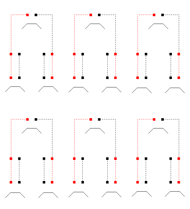 Figure 5: Surround sound with sounds equal in the front channels and
no sound in the rear channel
Notice in Figure 5 that current flows through the front speakers, in
one side and out the other. Current doesn't flow in the third speaker because
current is trying to flow in both sides at once.
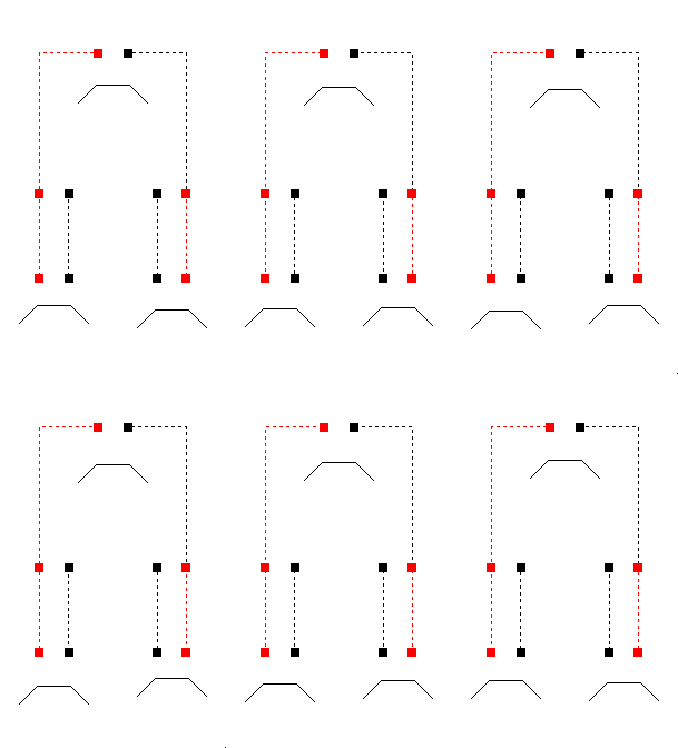 Figure 6: Surround with sounds only for the rear channel
With sounds encoded for the third channel, the current flows out of
phase for the front speakers. Notice in Figure 6 that when the current
flows out of phase in the front speakers, it is presented to the rear speaker
in such a way that it is able to flow through the speaker. Therefore, sounds
encoded for the rear speaker are also heard in the front speakers, but
are out of phase so they are difficult to locate. On the other hand, these
sounds are heard solidly in the rear speaker so are only perceived to come
from there. It actually works better if you use two speakers for the surround
channel. When two speakers are used for the surround channel, the black
(or -) wires are connected together as shown in Figure 7.
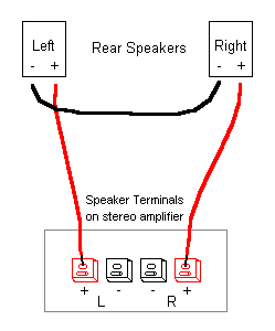 Figure 7: Decoding surround sound with two rear speakers
In the above example the regular stereo sounds are considered to be
equal, thus heard halfway between the front speakers and totally unheard
in the rear speaker. In reality, sounds are often unequal in the front
speaker and thus heard off center. With these sounds there is a proportional
leakage to the rear speaker. This has two effects: first, the off center
sounds are "pulled" farther off center; second, it adds a pleasing ambiance
to the sounds in the front speakers even when no third channel is encoded.
This is exactly what Radio Shack's Quatravox four channel simulator did.
If you happen to have a Quatravox it will decode surround sound.
Dolby Surround and Dolby Surround Pro Logic
So what about Dolby Surround® and Dolby Surround Pro
Logic®? Dolby Surround® adds a 20 millisecond delay
to the rear channel. This makes your room sound larger. Since the sounds
from the rear channel arrive late, it seems as though they came from a
greater distance. Pro Logic® add a sophisticated "gain riding"
amplifier to the system. This amplifier attempts to determine where the
loudest sound is and boosts the appropriate amplifiers to emphasize that
sound. The reason for this is to help solve the problem of signal leakage
from the front channels to the rear channels, as mentioned above. Mathematically,
there is only a 3db separation between the front and rear channels. Theoretically,
this separation would be barely detectable; you would have to listen hard
to tell that there was any difference at all. However, in reality the human
auditory system hears things differently.
First of all, any sound that is equal in the front channels (one which
would be centered between the two front speakers) is completely rejected
by the rear speaker (as mentioned above); it will not be heard in the surround
channel. Any sound which is out of phase between the two front channels
(as the surround channel will be) will be passed through and heard at full
volume in the rear speaker. Since the surround channel is out of phase
in the front speakers, the listener cannot distinguish where, in relation
the front speakers, the sound is coming from. As a result, by the time
the surround channel reaches your brain, it seems to come completely from
the rear speaker.
The second problem Pro Logic® attacks is that sounds toward
the edge of the TV screen tend to be pulled off the screen altogether;
someone talking near the edge of the screen will seem to be heard off screen.
This is once again caused by leakage of the front channel sound to the
rear channel. Pro Logic® adds a fifth speaker between the two
front speakers. This fifth speaker is fed with an equal mix of the front
channel signals, mixed in phase; sort of the opposite of the rear channel.
This pulls sounds back to the screen. Placing your front speakers close
to our TV helps solve this problem also. (Do not place them too close as
the magnets in the speakers will cause color shifts on the TV screen.)
Two Speaker Systems
There are some two-speaker surround sound systems on the market. These
systems use sophisticated phasing and time-delay circuits to fool the auditory
system into hearing sounds from points in space that are not between the
speakers. I have yet to listen to one of these system myself. Reviews in
magazines report that sounds that should come from behind actually come
from the side. They also report that some sounds come from random directions.
A four speaker system is cheaper and works better. (Lately, I've noticed
that two-speaker surround sound is being pre-encoded into some TV commercials.
In these commercials, with no surround sound decoding equipment at all,
sounds seem to come from places well outside the speakers.)
Front-to-Rear balance
Now, what about controlling the balance between the front and rear
channels? There are two basic approaches to this:
One approach would be to buy a second stereo amplifier for the rear
channel. Simply wire the speakers to both + or red terminals (leaving no
connection to the - or black terminals); A second method would be to wire
in a stereo fader (available from Radio Shack). These faders are designed
for automobile stereo systems and can handle only 25 Watts per channel.
However, all you have to do is wire in the fader according to Figure 8.
Figure 8 includes a switch to switch between surround mode and regular
stereo mode.
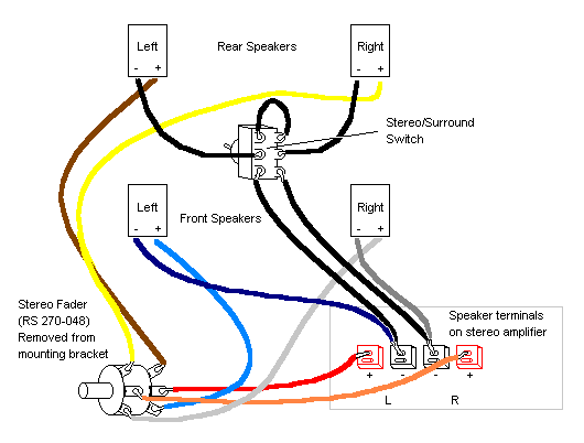 Figure 8: Wiring a stereo fader into the matrix
Balancing the System
In order for the above surround sound systems to work, the stereo balance
must be adjusted to null out the front channels in the rear speakers. To
do this: tune in an AM radio station (as mentioned above for checking the
phasing); disconnect the front speakers and adjust the speaker balance
control until the lowest possible sound level is heard in the rear speakers;
hook up the front speakers and you are ready to go. For the surround sound
to work properly this balance must be maintained.
Building an Active Decoder
Commercially made surround sound systems use an electronic circuit
called a differential amplifier to decode the surround sound. Since a differential
amplifier uses active electronic components, such as transistors, it is
considered "active".
The differential amplifier simply does, electronically, what the rear
speaker does in the passive decoder described above. The differential amplifier
rejects any signals that are identical in the front channels and pass any
differences to the rear channel. The output of the differential amplifier
is sent to the regular audio amplifier and then the rear speaker(s). One
advantage of this type of decoder is that you don't have to worry about
the null balance adjustment mentioned above. This adjustment is made in
the differential amplifier once and does not need to be readjusted.
If you want to take this route you can make a differential amplifier
with only four components, all available from Radio Shack (some Radio Shack
catalog numbers are given preceded with RS). With a few extra support components
a self-contained surround sound decoder can be built. The active decoder
is so simple that it can be built on a "breadboard" PC board also available
from Radio Shack. The full schematic is shown, including the pinout of
the IC, in figure 9.
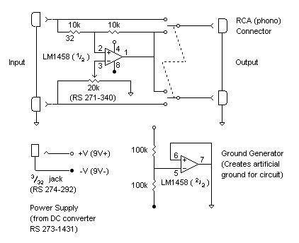 Figure 9: An active surround sound decoder
The circuit is powered by a 9V DC converter. The IC, however, is designed
to operate from dual power supplies. To make it work with a single power
supply an artificial ground is used. The artificial ground is generated
by using the second amplifier in the LM1458 IC as a voltage follower. A
voltage divider (two 100k resistors) established the ground point at 4.5V
(half of the 9 Volt supply). In the decoder circuit, the artificial ground
should be considered as zero Volts, the V+ as +4.5 Volts and the V- as
-4.5 Volts. However, since the circuit is actually powered from a single
power supply, the power input is labeled as +V (9V+) and -V (9V-) representing
the + and - terminals of the DC converter. Bus connections, such as +V,
-V and GND are shown by symbols only. This keeps the schematic from looking
too confusing.
The input of the active decoder is to be connected to the "Tape Out"
of your stereo amplifier. The output of the decoder will go to another
amplifier to drive the rear speaker(s). The DPDT switch can remove the
decoder from the system for regular stereo in both the front and rear speakers.
The null adjustment is made as described above for the passive decoder
except instead of adjusting the speaker balance the 20k 15 turn trim-pot
is adjusted.Wireless Surround Sound System
One thing you can also do with the active decoder is attach it to a
Ramsey Electronics FM-10x Stereo FM Transmitter. With this combination
you can transmit the surround channel to any FM radio for a wireless surround
sound system.
You can save some effort by wiring the active decoder right into the
FM transmitter. Power is derived from the transmitter's power supply (a
9 Volt battery if the transmitter is not modified). The RCA connectors
and the ground generator are eliminated, reducing the circuit to the four
components actually needed for the differential amplifier. The stereo/surround
switch could also be added to the transmitter.
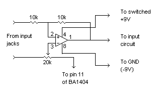 Figure 10: Decoder to add to Ramsey FM-10 stereo transmitter
Since I am unfamiliar with the newer versions of the FM-10x transmitters
I cannot give a wiring diagram. You will have to cut the circuit board
traces where the signals enter the transmitter and wire the decoder in
there. Pin 11 of the BA1404 IC acts as an artificial ground and is where
the GND connection of the decoder goes.
One More Thing
One unadvertised thing a surround sound decoder will do is reduce the
volume of the lead vocal in most popular music. Reduce the volume in the
front speakers and you have an instant karaoki machine.


