| Vocademy |
Early Radio Receivers
Coherer receivers
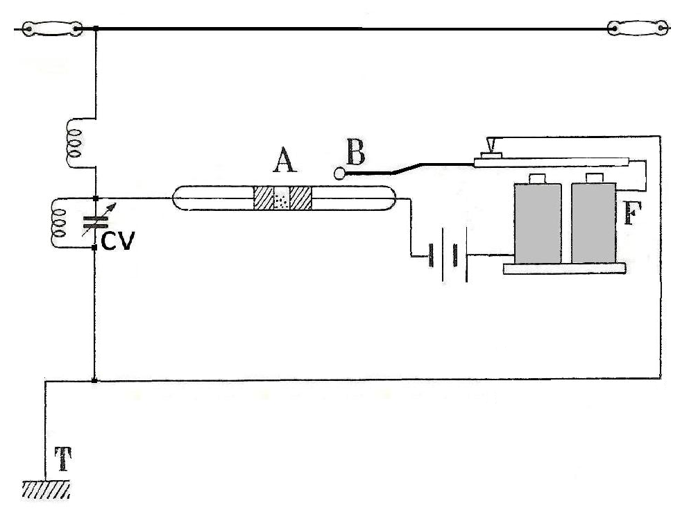
Early damped-wave receivers used a device called a coherer. This consisted of a glass tube containing metal filings. The coherer normally has a high resistance. When radio energy passes through the filings, the minute contact areas arc-weld together. This reduces the resistance dramatically. The simplest damped-wave receiver would place the coherer in a series circuit with a battery and an electric buzzer. When the coherer goes from a high resistance to a low resistance, it is like closing a switch. This completes the circuit to the buzzer. When the waves stop (when the transmitter operator lifts the code key) the coherer does not return to normal. The tiny welds need to be broken by lightly tapping the coherer. To facilitate this, a tapping device called a decoherer is attached to the buzzer's armature. Each time the buzzer is activated the decoherer lightly vibrates against the coherer, keeping the filings from remaining welded together.
 |
|
The principle of an early simple damped wave receiver. The coherer (A) activates the buzzer (F) when radio waves are received. The decoherer (B) vibrates with the buzzer, tapping the coherer to return it to its high resistance state. |
 |
|
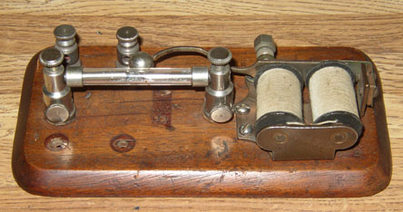
An actual coherer/decoherer |
Diode detector receivers
The coherer could only
detect the presence of radio waves. I could not follow the power variations that
Fessenden hoped to use to carry voice over radio waves. Even before building a
successful continuous wave transmitter, he developed radio wave detectors that
could receive what would later be called AM transmissions. The most successful
that Fessenden developed was the electrolytic detector. This consisted of a fine
platinum wire in contact with a platinum electrode submerged in a weak acid
solution. When electrical current passes in one direction, the detector has a
higher resistance than when current passes in the opposite direction (therefore,
the electrolytic detector was a diode). This could rectify radio waves and
produce a dc voltage proportional to the instantaneous power of the detected
waves.
Later, more practical
detectors were developed using silicon and galena crystals or vacuum tube
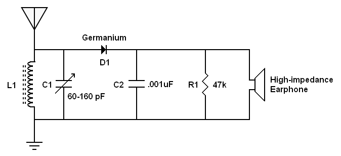
diodes. The following circuit is a modern version of these early receivers.
 |
|
A modern version of a crystal receiver |
Early AM receivers used
a diode and a capacitor to rectify and filter the radio signal. The diode acts
as a half-wave rectifier and the capacitor charges to the peak voltage of the
signal. This is much like the rectifier and filter of a power supply. The
difference is that the peak voltage of the signal is continuously changing as
the amplitude of the transmitter signal varies. In the above example, if the
transmitter is sending a 1 kHz tone, the voltage across the capacitor varies
1,000 times per second, recreating the original signal. A high-impedance
earphone is used because it produces an audible output with the tiny currents
extracted by the receiver.
The next generation of
AM receivers used an audio amplifier to produce an output strong enough to drive
a loudspeaker. Another improvement was to add a radio frequency amplifier before
the rectifier/detector so that weaker signals could be received.
Heterodyning
To understand the next
generations of receivers you need to understand heterodyning. This is where two
signals can be mixed to produce new signals.
When two frequencies are
mixed together the result is two new additional frequencies. You may
occasionally hear a twin-engine propeller-driven aircraft with its engines
out-of-synch (this is not common; it is bad form to let it happen). If you hear
it, you will hear the characteristic beat as the sounds of the two engines
interfere with each other.
The following diagram
illustrates what happens. Each of the overlapping vertical lines represents a
sound pulse from one engine. In the following case, one engine is causing pulses
100 times per second and the other is causing pulses 104 times per second.
Notice that sometimes the pulses happen at the same time but other times they
alternate. When they happen at the same time we get a doubly-strong pulse; when
they are alternating, there is no definite end of one pulse before the beginning
of the other, which weakens the overall strength of the pulses. With sine waves,
when the waves are entirely out-of-synch (180° out-of-phase), one wave cancels
the other.
 |
|
Two frequencies of 100 Hz and 104 Hz interact with each other creating a periodic interference pattern (a beat frequency) at a frequency of 4 Hz. This illustration shows the interaction for ½ second so you can see two cycles of the beat frequency. |
With one set of pulses
occurring at 100 Hz and the other set occurring at 104 Hz, the pulses cycle from
a state of being together to an alternating state four times every second. This
causes a pulsing of energy at a frequency of 4 Hz. This third frequency is
called a beat frequency. In the case of engines being out-of-sync, this pulsing
four times each second would be very annoying to anyone on the aircraft, which
is why running the engines out-of-synch is to be avoided. There would be yet
another frequency produced, which would be 204Hz. Notice that the two new
frequencies are at the sum of the two original signals (204Hz) and the
difference (4 Hz). The difference frequency is much easier to illustrate, as
shown in the illustration.
If you want to
demonstrate this to yourself, hum together with a friend at the same pitch. Once
you are clearly together, one of you slowly change your pitch while the other
doesn't change. You will undoubtedly hear the beats when one of you drops
out-of-synch.
This phenomenon is
useful in two technologies for radio receivers. The first is the product
detector receiver and the second is the Superheterodyne receiver.
The product detector receiver
The second generation of
radio receivers used diode detectors instead of coherers (as shown above). Such
receivers work well with AM because the rectified and filtered radio signal is a
DC voltage that, at any instant in time, is directly proportional to the power
of the radio signal. Therefore, as the power varies with amplitude modulation,
the receiver recreates the "voice-shaped currents" that were used to modulate
the signal.
Such a receiver doesn't
work well with CW (Morse Code) transmissions. Since the transmitter is just
turned on and off with a telegraph key, the output of the receiver is just
pulses of DC voltage. All that is heard in the earphone is faint clicks. You may
think that this on-and-off DC voltage could be used to operate a buzzer as the
coherer receivers could. However, the coherer worked as a switch; there was a
battery in the circuit to operate the bell or buzzer. The diode detector doesn't
extract enough energy from the radio waves to operate a bell or buzzer. Before
amplifiers were invented, the diode detector receivers could not work well with
CW transmission.
One solution for CW
reception was the Beat Frequency Oscillator (BFO). Instead of rectifying and
filtering the received signal, an oscillator is run at nearly the same frequency
as the transmitter. For example, to receive a CW signal at 1MHz, the receiver
has an oscillator that operates at, for example, 1.001MHz. This is 1kHz above
1MHz (1MHz is 1,000,000Hz and 1.001MHz is 1,001,000Hz). Therefore, the
difference between the two frequencies is 1,000Hz (1kHz). When you mix the 1MHz
from the transmitter with the 1.001MHz at the receiver, you get a beat frequency
of 1kHz. This is heard plainly in the earphone. Therefore, whenever the
transmitter is on (when the transmitter's operator is pressing the telegraph
key) the receiver's operator hears a 1 kHz tone in the earphone. The receiver's
operator can vary the tone by varying the BFO frequency.
| Vocademy |
