| Vocademy |
Antennas
This lesson covers the fundamentals of several types of antennas that you may encounter. However, it is not comprehensive only covering the basics. For a practical guide to making amateur radio antennas see The ARRL Antenna Book.
As mentioned in Electromagnetic Waves above, radio waves for communication are produced by getting a wave of electrical current to bounce back and forth along a wire. Let's assume the wave in the wire travels at the speed of light. If the wire is 150 meters long, it takes one microsecond (one-millionth of a second) for the wave to make one round trip in the wire. Therefore the wave will make 1,000,000 round trips per second. This creates an electromagnetic wave with a frequency of 1,000,000 cycles per second or 1 MHz. That electromagnetic wave travels away from the antenna at 300,000,000 meters per second. In one microsecond, the time it takes to complete one cycle, it travels 300 meters. Therefore its wavelength is 300 meters (by definition, the wavelength is the distance the wave travels during one cycle).
In reality, the electric wave in the antenna travels slower than the speed of light. Therefore, to create an electromagnetic wave at a frequency of 1 MHz, the wire must be shorter than 150 meters. The speed of the electric wave in the antenna divided by the speed of light in a vacuum is called the velocity factor. That is affected by the antenna construction, the frequency of the wave, and other factors. If the velocity factor is 0.95, meaning the electric wave in the antenna travels at 95% of the speed of light, the antenna must be 143 meters long to operate at 1 MHz. This shortened antenna has an electrical length of 1/2 wave even though it is physically shorter than 1/2 wave at its operating frequency. In the descriptions below, the velocity factor is ignored for simplicity. However, when building a working antenna, the velocity factor must be determined and factored into the antenna length calculations.
Most antennas are resonant antennas. The electric wave becomes a standing wave in the antenna much like the sound wave in a vibrating guitar string. Such an antenna acts as a parallel resonant circuit. Therefore, an antenna that operates at 1 MHz acts like an inductor and a capacitor in parallel, making a tank circuit that resonates at 1 MHz. Like any resonant circuit, an antenna resonates at a lower frequency if you increase the inductance or the capacitance. If the antenna is longer than the ideal length, it resonates at a frequency lower than the operating frequency. This is intuitive since it takes longer for the electric wave to travel the length of the antenna. However, an alternate way to analyze such an antenna is that being too long, it has too much inductance and capacitance to resonate at the desired frequency; increasing the inductance or capacitance lowers the resonant frequency. If a particular installation requires an antenna too short to resonate at the required frequency, its resonant frequency can be lowered by adding inductance or capacitance. This is covered in Loaded Antennas below.
In the above example, the 150-meter antenna creates electromagnetic radiation with a wavelength of 300 meters. This constitutes a 1/ 2 wavelength antenna. The length of an antenna may be specified by wavelength or degrees. For example, a 1/2 wavelength antenna may be specified as a 180-degree antenna. A 5/8 wave antenna may be specified as a 225-degree antenna.
Antenna gain
A theoretical antenna, called an isotropic radiator, radiates evenly in all directions. With an isotropic radiator, the power of the radiated energy would decrease with the inverse square of the distance from the antenna; if you double your distance from the antenna, the received power will decrease by a factor of four. All real antennas concentrate their radiation in one way or another. For example, a vertically mounted monopole or dipole antenna (described below) will concentrate its radiation along the horizon. Therefore, if you are receiving from a point along the horizon, you will receive a stronger signal than if you are above the antenna; the power projected along the horizon is stronger than from an isotropic radiator. So, if you are in the right place, a monopole or dipole antenna seems to produce a stronger signal than an isotropic radiator. This is called antenna gain.
Antenna gain may be measured where the signal is the strongest or from where the receiver is expected to be. For example, a vertically-mounted monopole or dipole antenna placed close to the ground will tend to radiate at an upward angle. Since receivers tend to be along the horizon, the gain is measured from along the horizon, not from where the radiation is strongest.
Antenna gain is measured in decibels compared to one of two references. Gain compared to an isotropic radiator is measured in dBi, and gain compared to a dipole antenna is measured in dBd. For example, if you measure the signal from an antenna and get a maximum signal of twice the expected power from an isotropic radiator, your antenna gain is 3 dBi[1].
Radiation patterns
A vertically-mounted dipole or monopole (with nothing nearby to affect
its radiation pattern) will radiate roughly along the horizon in all
directions of the compass. Some such antennas may radiate some energy at
an upward angle but what radiation goes toward the horizon goes evenly in
all directions. This is called an omnidirectional antenna.
Vertically-mounted monopoles, dipoles, and ground plane antennas are
omnidirectional antennas.
If a dipole antenna is mounted horizontally, that radiation pattern
rotates 90 degrees. Now the radiation, going perpendicular to the antenna,
goes in one direction along the horizon, overhead, then in the opposite
direction along the horizon. If that antenna is mounted with the wire
going north to south, the radiation will go due east, directly overhead to
due west. Therefore, along the horizon, it radiates two directions, east,
and west. This is a bidirectional antenna.
The following graph shows the radiation pattern of a horizontal dipole
antenna. This is a polar graph, meaning that the grid is made of
concentric circles with radial lines indicating the directions of the
compass[2].
The oval lines represent the signal strength in different directions. The
farther a point is from the center, the stronger the signal. Such a plot
is made by measuring the signal strength going around the antenna in a
circle, with the antenna at the center, and plotting the signal strength
at many points around the circle.
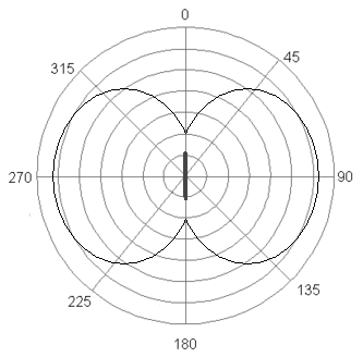 |
| The radiation pattern of a horizontally-mounted dipole antenna. The antenna is oriented north and south, as indicated by the heavy line. |
Here, with the antenna wire going from north to south (0 degrees to 180
degrees), the radiation is strongest going east and west (90 degrees and
270 degrees). Measured from the northeast (45 degrees), the radiation is
about 80 percent as strong as that going directly east. It's the same
going southeast at 135 degrees, southwest at 225 degrees, and northwest at
315 degrees. Measured from north-northeast (22.5 degrees), the signal
strength is down to about 60 percent. It is the same going
south-southeast, south-southwest, and north-northwest. Practically no
radiation goes directly north or south off the ends of the antenna. If the
antenna is rotated horizontally, the radiation pattern rotates with it.
If the above antenna wire is mounted vertically, the radiation then goes
toward the horizon evenly in all directions. It is then an omnidirectional
antenna. The following graph is for an omnidirectional antenna.
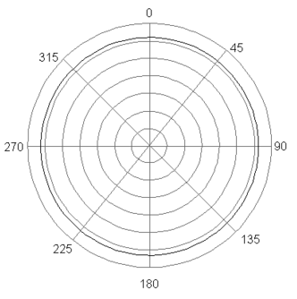 |
| Radiation pattern of an omnidirectional antenna |
The plot is a circle since the measured radiation is equal in all directions.
Other directional antennas have corresponding radiation patterns and will be shown as needed below.
Radiation resistance
The product of voltage and current is power. Power is manifested by the production of either heat, mechanical motion, or electromagnetic radiation. An antenna produces both heat and electromagnetic radiation. Naturally, you want to maximize electromagnetic radiation and minimize heat. Whatever power is dissipated by an antenna that is not manifested as heat is manifested as electromagnetic radiation. Heat is produced when current flows through the actual resistance of the material of which the antenna is made. That resistance is called ohmic resistance. Let's say you have a magic antenna with zero ohms of ohmic resistance. You still have voltage and current producing electromagnetic radiation. Ohm's Law states that voltage divided by current equals resistance. Yet you have no resistance. We call this fictitious calculated resistance radiation resistance. Therefore, radiation resistance is a good thing that promotes desired electromagnetic radiation—more radiation resistance results in better performance.
Different antenna configurations have different amounts of radiation resistance (the particulars are beyond the scope of this lesson). Also, antennas with greater diameter elements tend to have less ohmic and, therefore, more radiation resistance. Electrically short antennas—meaning antennas significantly shorter than 1/2 wavelength—also have relatively low radiation resistance[3]. An antenna close to the ground has losses due to interaction with the ground called ground losses. Since these losses result in less radiation, they reduce the radiation resistance. Therefore, the calculated radiation resistance of a particular antenna assumes the antenna is mounted in appropriate proximity to the ground. For example, a dipole antenna (see below) is assumed to be in free space several wavelengths above the ground. A monopole (see below) is assumed to be mounted above a perfectly conducting ground plane.
Polarization
As explained in the section on electromagnetic waves, an electromagnetic
wave's polarization is the electric field's orientation. Most antennas,
being lengths of straight wires or equivalent, produce a voltage field
along the length of the antenna. Therefore, a vertically oriented antenna
produces vertically polarized waves. Likewise, a horizontally oriented
antenna produces horizontally polarized waves. The receiving antenna
should be oriented to match the waves it receives. At microwave
frequencies, waves polarized perpendicularly to the antenna are rejected
such that two signals can be sent on the same frequency if they are
cross-polarized.
As explained below, the electromagnetic waves from turnstile antennas
radiating perpendicular to the plane of the elements are circularly
polarized; the polarization rotates 360 degrees with each cycle. Helical
antennas also produce circularly polarized waves.
Long wire antennas
As its name says, this is just a length of wire with little thought of its wavelength. It is often a wire strung between the transmitter building and a convenient support such as a tree. These antennas are usually used on the lower HF and MF bands and below, where an antenna of the appropriate wavelength is impractical. When used for transmitting, an impedance matching device must be connected between the antenna and the transmission line.
Random wire antenna
As its name says, this is just a random length of wire that is less than 1/4 wavelength of the operating frequency.
Long wire antenna
A long wire antenna is like a random length antenna, except its wavelength is at least 1/4 wave. Some consider that it must be at least one wavelength long.
Beverage antenna
A beverage antenna (named after Harold Beverage) is a long wire receiving antenna strung horizontally between two supports. The far end of the antenna is connected to the ground through a resistor. It receives strongly in the direction the wire is pointed away from the receiver. A beverage antenna may use a horizontal counterpoise wire as an artificial ground instead of being connected to the earth.
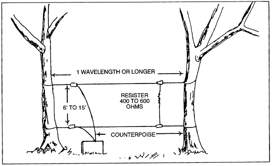 |
| A beverage antenna using a counterpoise instead of being grounded. |
Unlike most antennas, which are resonant antennas, the beverage antenna
is a traveling wave antenna. As the electromagnetic wave encounters the
antenna, it sets up a voltage wave that travels from the far end to the
receiver. The resistor absorbs the energy of any waves going in the
opposite direction. This makes the antenna unidirectional. Since the
beverage antenna doesn't resonate at a particular frequency, it also has a
wide bandwidth.
Monopole and dipole antennas
As described above, an antenna consisting of a straight wire is a half-wave monopole[4] antenna. The wave of current in the antenna travels from one end to the other and back to complete one cycle. So, although the antenna length is 1.5 meters for 100 MHz, the wave makes a round trip of 3 meters to complete one cycle. Also, the radio wave emitted into free space travels 3 meters in the time it takes to complete one cycle. Therefore, by definition, the wavelength of the radio wave is the distance it travels during one cycle. If the wavelength of the radio wave is 3 meters, a suitable monopole antenna will be 1.5 meters long or one-half wavelength. However, practical antennas may differ slightly from the ideal to control factors such as the vertical radiation angle.
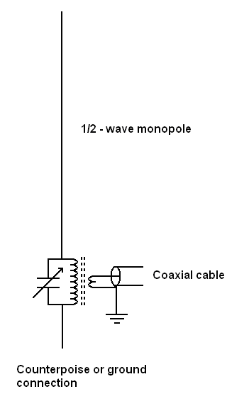 |
| An end-fed half-wave monopole with matching transformer. |
Most of the radio energy emitted from a half-wave antenna appears to
travel away from the antenna in a direction perpendicular to the wire.
Very little energy is radiated off the ends. If the antenna is oriented
vertically, the radio waves travel horizontally in all directions of the
compass, like ripples from a stone dropped into a pond. Such an antenna is
said to be omnidirectional. Some monopole or dipole antennas mounted close
to the ground will radiate significant energy at an upward angle. For that
reason, monopole antennas are often mounted several wavelengths above the
ground. Monopole antennas mounted close to the ground my have a length
that differs from the theoretical ideal length. This non-ideal length
lowers the efficiency of the antenna slightly, but also lowers the
radiation angle.
The polarization of a radio wave is said to be the orientation of the
electric field. A monopole or dipole will produce a wave with the electric
field parallel to the antenna. Therefore, a monopole or dipole antenna
oriented vertically will produce vertically-polarized waves. For the
highest efficiency, a receiving antenna should be oriented to the same
angle as the waves it receives.
The end-fed half-wave monopole antenna
Recall that there is a relatively high voltage at the ends of the
antenna wire. This is because, as the wave of current travels back and
forth in the wire, the electrons bunch up at the ends. This voltage must
be overcome to feed the antenna from the end. Therefore, it takes a
relatively high voltage to inject current into the antenna. This means the
antenna has a relatively high impedance.[5] The impedance of an end-fed half-wave monopole is approximately 1,800 ohms
to 5,000 ohms.
An end-fed half-wave monopole antenna is usually coupled to the
transmission line through a transformer to compensate for the high
impedance of the antenna. This is often a toroidal transformer (a
transformer wound on a ferrite ring [a toroid]).
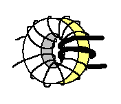 |
| A toroidal transformer |
The secondary winding of such a transformer is often part of a tuned circuit. Other matching devices, as discussed below, may also be used to couple the transmission line to an end-fed monopole. Suppose the antenna is not connected to the ground. In that case, it will usually have a short section of wire called a "counterpoise" (counterbalance) on the opposite side of the secondary winding to the antenna.
The end-fed 5/8 wave monopole antenna
The 5/8 wave monopole is a very popular type of antenna. This is because, if it is close to the ground, its radiation pattern is lower to the horizon than a half-wave monopole. This lower radiation pattern leads to higher gain, which is about 2.1 dBi. One problem with a 5/8 wave monopole is that it radiates some energy upward at about 60 degrees above the horizon. This can lead to multipath fading in the medium frequency band and lower when that radiation reflects off the ionosphere to the fringe of the ground wave. Other than the length, a 5/8-wave monopole is constructed and fed about the same way as a half-wave monopole.
The center-fed half-wave open dipole antenna
The half-wave monopole can be split at the center to create a half-wave dipole. This type of antenna is fed by a balanced signal at the split, which is ideal for connection to twin-lead transmission line. While one wire carries current to the antenna, the other wire carries current away from the antenna. Due to the right-angle turn of the current path where the transmission line meets the antenna, the current travels in the same direction in both halves of the antenna at any one time (keep in mind that the current is reversing direction at the frequency of the radio signal.
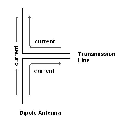 |
| In a half-wave open dipole antenna, at any moment in time, the current travels one direction in the antenna and opposite directions in the twin-lead transmission line. |
An open dipole has an impedance of 50 to 75 ohms. Twin-lead has a balanced signal but has an impedance of 300 to 600 ohms. This means that a half-wave open dipole antenna is unsuitable for being fed with twin lead. A half-wave open dipole can be fed with 50-ohm coaxial cable. However, the outer conductor of a coaxial cable carries no signal since it is grounded (the signal is unbalanced). The only current in the half of the antenna connected to the outer conductor is induced current from the other half of the antenna (through electromagnetic coupling). This induced current can travel back through the outer conductor, causing undesireable radiation from the transmission line. To get efficient radiation from an open dipole fed with coaxial cable, you need a device that converts the unbalanced signal to a balanced signal. Such a device is called a balun (from BALanced and UNbalanced).
A common type of balun is a transformer. This is similar to the transformer used for end-fed monopoles. Such baluns, sold commercially for VHF (e.g., television), are sometimes called matching transformers. This type of balun has a wide bandwidth, so it can be used over a wide range of frequencies.
 |
| A common transformer-type balun |
Another type of balun is a half-wave-long piece of coaxial cable connected between the two halves of the dipole. This length of coax delays the signal such that the current travels in opposite directions when it reaches the antenna. This balun works well only at the frequency where the cable length is one-half wavelength. Therefore it is narrow-banded, working well only at or near a single frequency.
 |
| A half-wave open dipole with a coaxial balun. |
Folded dipole
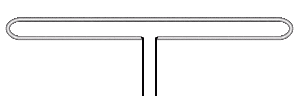 |
| The center-fed half-wave folded dipole antenna |
Another type of center-fed half-wave dipole is the folded dipole. This type of antenna is a "flattened" ring of wire one wavelength long. One advantage of this antenna is that it has an impedance of 300 ohms. Therefore it can be directly fed with 300-ohm twin-lead.
The radiation patterns for monopole and dipole antennas are illustrated in Antenna gain and radiations patterns above.
Loop antenna
A loop antenna is what its name says. The most straightforward loop
antenna is essentially a folded dipole that has been opened up. This is
considered a large loop because the total length of wire is one wavelength
or more. A small loop has a total wire length significantly less than 1/2
wavelength at its operating frequency. The terms "large" and "small" do
not relate to the antenna's physical size. A large loop for VHF or UHF may
be physically tiny compared to a small loop for MF or HF. The shape of the
loop has little or no effect on the characteristics of the antenna. They
may be circular but are often square because it is easy to stretch a loop
of wire around a cross-shaped support.
The size, feed point, and other factors control many properties of loop
antennas. This is beyond the scope of this class, but the basics are
covered below.
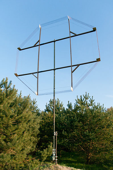 |
| This 2.7-meter-diameter antenna is a "small" loop operating on the LF (1000 meter) and MF (100 meter) bands. |
Small loop antenna
Small loops have characteristics like inductors. They have low radiation resistance, so they are not efficient for transmitting or receiving. However, they are useful for radio direction finding. A small loop antenna radiates or receives most strongly along the plane of the loop. However, they have a sharp null point broadside to the loop where the radiation and reception are virtually zero. Therefore, when a small loop antenna is rotated until the received signal is at its weakest, the source of that signal is directly broadside to the antenna.
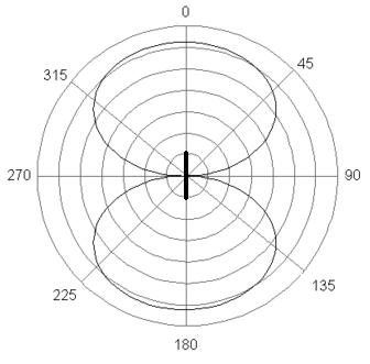 |
| The radiation and reception pattern of a small loop antenna with its plane oriented north and south as indicated by the heavy line. Notice the deep null between the lobes. |
A small loop antenna may be one or more turns of wire, but the total length of the wire must be much shorter than 1/2 wavelength to be considered a small loop. The loop is often made of a length of coaxial cable with one end of the shield grounded (if both ends are grounded, the shield will block the radiation to and from the antenna). The center conductor acts as the antenna, and the shield blocks electric fields that reduce the directional characteristics of the antenna.
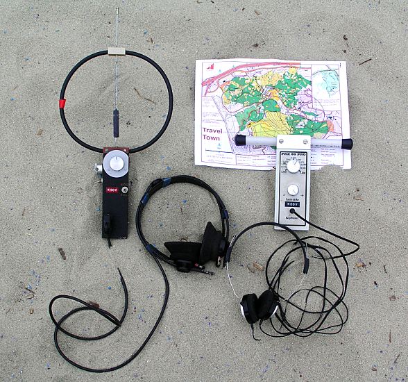 |
| A handheld loop antenna, amung other tools for radio direction finding. |
Large loop antenna
1/2-wave large loop
A large loop antennas consist of a wire that is at least 1/2 wavelength. They are often square-shaped because it is easy to stretch a wire on the perimeter of an X-shaped spreader. The feed point is usually in the center of one leg of the loop. A large loop antenna with a wire length of 1/2 wavelength radiates along the plane of the loop, similar to a small loop. However, it radiates in a direction away from the feed point. If the side of the wire opposite the feed point is opened, the radiation is in the opposite direction. Unlike a small loop, there is no direction where the radiation is zero.
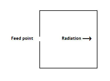 |
| A half-wave large loop radiates strongly away from the feed point along the plane of the antenna. |
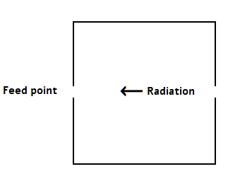 |
| A half-wave large loop that is broken opposite to the feed point radiates strongly toward the feed point. |
Full-wave large loop
A large loop antenna with a wire length of one wavelength has an impedance of about 100 ohms compared to a folded dipole which has about 300 ohms of impedance. The radiation pattern of a large loop antenna is strongest broadside to the loop.
 |
| A large loop radiates broadside to the plane of the loop. The pattern is nearly the same as a dipole antenna. |
The feed point can be either in the center of one leg or at a point of the square. If the feed point is in the center of a leg, the polarization is parallel to that leg. If the feed point is on the point, the polarization is parallel to a line between that point and the opposite point.
Turnstile antenna
Recall that a monopole or dipole antenna radiates energy perpendicularly to the length of the antenna wire. If a dipole antenna is mounted horizontally, it radiates in two directions horizontally. This means that the antenna can be aimed along the horizon. However, the signal will also be horizontally polarized. Therefore, the receiving antenna should also be mounted horizontally.
A turnstile antenna can be used if you want a horizontally polarized signal that is also omnidirectional. The antenna is two dipole antennas mounted perpendicular to each other, with the two antennas fed 90 degrees out-of-phase. The resulting radiation pattern is nearly omnidirectional if the antenna is mounted horizontally.
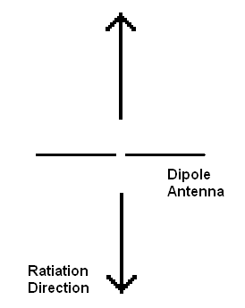 |
| Looking down toward a horizontally-mounted dipole antenna. |
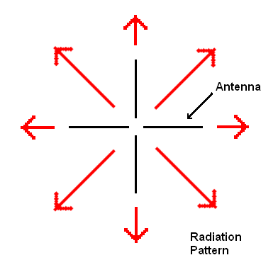 |
| A horizontally-mounted turnstile antenna viewed from above. |
The turnstile antenna also radiates perpendicularly to the elements. That means a horizontally-mounted turnstile antenna will radiate straight up as well as along the horizon. The vertical radiation will be circularly polarized. This means the polarization will rotate around a complete circle with each wave cycle. This polar rotation happens because each antenna radial has the voltage 90 degrees before or after the adjacent radials. When these voltage components add together vectorially, a single voltage component rotates around the four radials once for each wave cycle.
The following illustration shows the voltage component traveling back and forth in each element (shown as groups of electrons as in the original illustration of voltage and current in Radio Transmitters above). Following the diagrams from top left to bottom right, the rotating arrow illustrates how the electrons combine to create a rotating voltage component viewed from above the antenna.
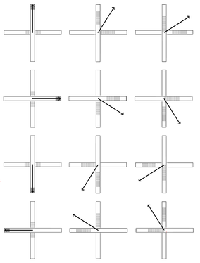 |
| Turnstile antenna showing the waves of electricity and the voltage vector over one cycle. |
Turnstile antennas are often used for satellite communication. This is because satellites are often spin-stabilized. Normally, the radio waves coming from the satellites would rotate as the satellite rotates. The earth station antenna would then need to rotate along with the satellite to receive the signal. Using circular polarization eliminates this problem.
Bow-tie and bi-conical antennas
A bow-tie antenna is a dipole antenna widened toward the ends with flattened elements. This widening increases the bandwidth of the antenna.
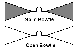 |
| Bowtie antennas |
If the elements are cone-shaped, this is called a biconical antenna.
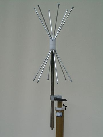 |
| An open biconical antenna |
Bow tie and biconical antennas are dipole antennas and radiate as such.
One-quarter wave ground plane antenna
A 75-meter-long wire in free space will resonate at 2 MHz and can be used as a 1/2 wavelength antenna at that frequency. However, if that antenna is a 75-meter half-wave monopole and is placed vertically upon the earth (fed from the earthbound end), it will act like a 150-meter 1/2 wave dipole antenna.
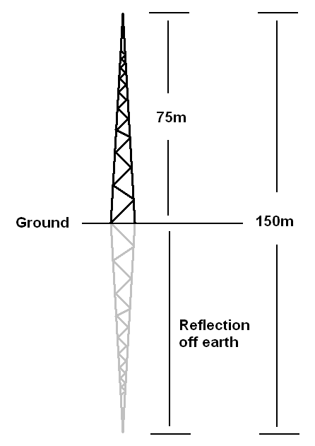 |
| A quarter-wave ground plane tower antenna for the middle of the AM broadcast band at 1,000 kHz (ignoring the velocity factor). |
Several competing theories explain why an antenna acts twice as long when one end is upon the earth. One theory claims that the earth (or artificial ground plane) works like a reflector. The antenna and its reflection in the earth are twice the length of the antenna alone. That is the theory illustrated above. Another theory is that the earth's proximity increases the antenna's capacitance, thus cutting the resonant frequency in half. Yet another theory is that the earth or artificial ground plane acts as the second half of a dipole antenna, only flattened out.
The above example is a large antenna mast where the mast itself is the antenna (see Mast Radiators below). Such large quarter-wave ground plane antennas may be used in the lower range of the HF band and below. However, tower antennas may be monopoles of various fractions of a wavelength or quarter-wave ground plane antennas.
Small ground plane antennas often have an artificial earth (artificial ground plane). This consists of horizontal radial wires at the base of the vertical element. The artificial ground plane may be flat but is often angled downward. The angle controls the impedance, bandwidth, and radiation angle as needed. Ground-mounted antennas sometimes have radial wires laid out on the ground to improve the ground plane conductivity.
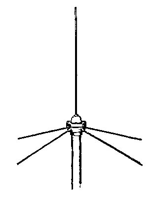 |
| A pole-mounted ground plane antenna |
Discone antenna
A Discone antenna can be thought of in two ways. First, it can be considered a bi-conical antenna where one element is flattened to a disk. Second, it can be viewed as a ground plane antenna where the vertical element is flattened to a disk. A Discone may be made from sheet metal or individual wire elements arranged in the same shape.
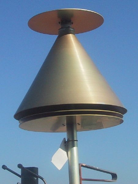 |
| A solid sheet metal discone antenna |
The Discone has no gain and an exceptionally-wide bandwidth, in the order of 10:1 (e.g., a single Discone antenna could operate over the range of approximately 100MHz to 1GHz).
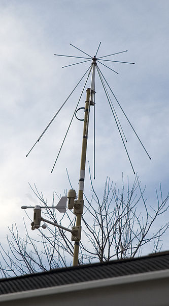 |
| A small rooftop open discone antenna. |
 |
| A discone antenna on the battleship USS Missouri. The cone part is made from supported wires. |
Ground plane and discone antennas are omnidirectional.
Voltage and current distribution along an antenna
In Radio Transmitters previously, there is an illustration of electrons bouncing back and forth along a wire. This is a good illustration to show the basic operation of an antenna. However, the electrons moving in the antenna may be better-illustrated like water sloshing back and forth in a bathtub.
 |
| Water has been pushed toward one end of the tub, causing a higher water level at that end. |
 |
| Gravity at the high end pushes the water down and forces it to flow toward the opposite end. So at one point, the water is level but moving toward the opposite end. |
 |
| Inertia causes the water to bunch up at the opposite end. Gravity then causes the water to reverse direction. |
 |
| Once again, the water becomes level but moves toward the original end. Inertia again causes the water to bunch up, and the cycle repeats. |
Notice that the water level and head pressure change dramatically at the tub's ends. This is analogous to the voltage at the ends of the antenna, where there is a relatively high AC voltage. However, the water level in the middle doesn't change. The water just passes back and forth there. This is analogous to the middle of an antenna where the AC voltage is negligible, but there is a significant AC current.
The following graph shows the current and voltage distribution along a dipole antenna.
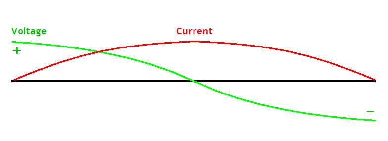 |
| Voltage and current along a dipole antenna. |
This is a typical diagram you may see in publications about antennas (although it may be rotated vertically). The graph may be confusing to the novice, but it is useful for showing the voltage and current distribution and, thus the impedance distribution on both simple and complex antennas. The black horizontal line represents the dipole antenna. The graph shows the current and voltage distribution at two different times, the moment of maximum voltage and the moment of maximum current. The above graph shows the voltage distribution when the electrons are bunched up on the right side. Therefore, the voltage is at its negative maximum on the right and positive maximum on the left, with no voltage in the middle. At that moment, there is no current in the antenna because the electrons have stopped moving as they reverse direction. The current is shown at the time of maximum current. This is analogous to the bathtub model when the water is level but moving toward one of the ends. There is no voltage differential along the antenna at that time. Some versions of this graph may show a current direction based on the voltage polarity. However, this is ambiguous because the presence of voltage and current occur at different times (90 degrees out of phase[6]).
Here is an animated version of the graph from Wikipedia.
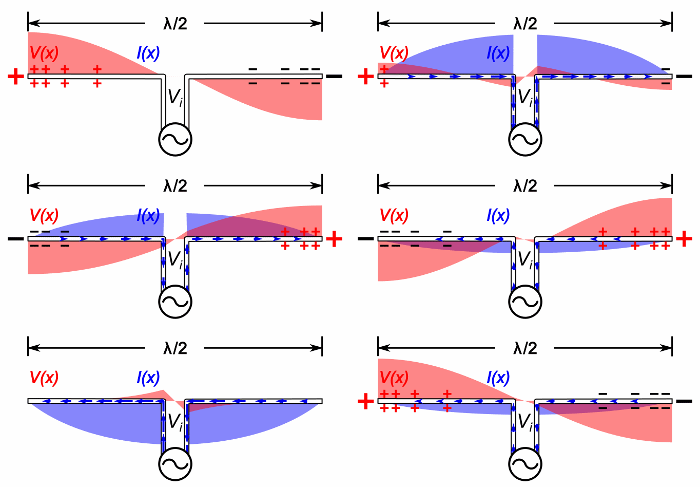
An animation of the voltage and current along a dipole antenna from Wikipedia
This shows the AC nature of the voltage and current. Keep in mind that the graph uses distance from the antenna to represent the magnitudes of voltage and current. It does not represent the positioning of anything in the space around the antenna.
The point to remember is that when the antenna is either transmitting or receiving, there will be different AC voltages and currents along the antenna. This translates to different impedances along the antenna. Assume that we have equipment that can measure the voltage and current at any point along the dipole. Let's say that at 10 centimeters from the center, we find an AC voltage of 0.001 volts (compared to the center of the dipole) and a current of 0.00002 amps. Ohm's Law tells us we have an impedance of 50 ohms at that point. As we move away from the center, the impedance increases. As we move closer, it decreases. This may be surprising since the antenna is a short circuit to DC. However, as in inductors, a short circuit to DC is not necessarily a short circuit to AC.
The following is a similar diagram from Wikipedia showing the voltage and current distribution with a J-pole antenna. This diagram uses a common notation where 1/2 wavelength is signified by the Greek letter lambda over the numeral two (λ/2), etc.
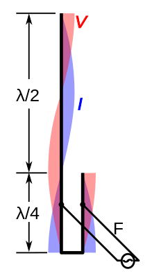 |
| Voltage and current along a J-pole antenna. The transmission line connects where the antenna impedance matches the transmission line impedance |
Antenna Matching
The antenna impedance must match the transmission line impedance for the greatest power transfer. As noted above, some antennas perfectly match certain transmission lines. For example, the folded dipole has an impedance of 300 ohms which perfectly matches 300-ohm twin lead transmission line. Most antennas don't have such a convenient impedance and must have a matching device between them and the transmission line.Transformer match
The 1/2 wave and 5/8 wave monopoles usually use a matching transformer (see Monopole and dipole antennas above). This steps up the voltage to that necessary to feed an antenna from the end but also acts as an impedance matching device. A transformer-type balun also acts as a matching transformer and is often called a matching transformer rather than a balun.
Delta match
A delta match connects twin lead to an open dipole antenna. In this case, the dipole consists of a single intact metal rod or tube. The twin lead is attached to the antenna element at two points approximately 0.12 wavelength from the center of the antenna. The twin lead's connection forms a triangle (looking like the Greek letter Delta) with the sides at an angle of approximately 45 degrees.
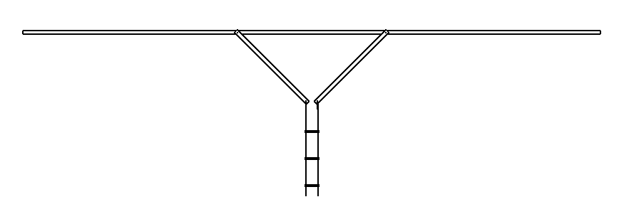 |
| An antenna with a delta match |
At first glance, the transmission line appears to be shorted by the
antenna. However (as noted above), what is a short circuit to DC may
present some impedance other than zero ohms with AC. The delta match is
usually attached to the antenna element by clamps so that the attachment
points can be adjusted and the match tested until the antenna has the
maximum power output or the lowest reflected power. At that point, the
antenna impedance matches the transmission line impedance, which is either
300 or 600 ohms.
The delta-shaped part of the delta match acts as an antenna itself; it
radiates radio waves in addition to the antenna. These radio waves
interfere with the waves coming from the antenna. This causes more
radiation to be directed toward the ends of the antenna rather than
perpendicular to the antenna. This may be an advantage or a disadvantage
depending on where you want your radiation to go. Also, there is no
practical way to calculate the attachment points or the lengths of the
delta elements. They must be determined by experimentation. This can be a
time-consuming process.
T match
The T match is a variation of the delta match.
 |
| An antenna with a T match |
The advantage of the T match is that it doesn't change the antenna's radiation pattern as a delta match does. This is because the matching elements are close to and parallel to the dipole and thus don't radiate separately from the dipole.
If the dipole element is the correct length for the operating frequency, adding a T match will increase the inductive reactance of the system. This can be compensated by shortening the dipole element, but that will decrease the radiation resistance. The more popular solution is adding series capacitors between the transmission line and the T elements.
Gamma match
A gamma match is a variation of the T match suitable for use with coaxial cable.
 |
| An antenna with a gamma match |
The coaxial shield is attached to the center of the antenna element,
where the voltage is zero volts. The center conductor is connected to the
gamma match.
Like the T match, the gamma match increases the inductive reactance of the
system. When a capacitor is placed in series with the transmission line,
that capacitor is often part of the gamma match construction. The coaxial
cable is coupled to the gamma match by a larger diameter tube and
insulated by a layer of plastic.
 |
| Gamma match with capacitor |
The gamma match (the inner tube) is adjusted in and out of the larger tube to change the capacitance while adjusting for the maximum power output or minimum reflected power.
The J antenna
The J antenna, commonly called a J-pole, is a 1/2-wave end-fed monopole fed with an impedance matching stub, a 1/4-wave-long section of parallel conductors shorted at one end. These conductors, being parallel and properly spaced, constitute a short length of transmission line. The usual construction of a J-pole antenna is a single 3/4 -wave rod or tube with an L-shaped extension making the entire antenna J-shaped, hence the name.
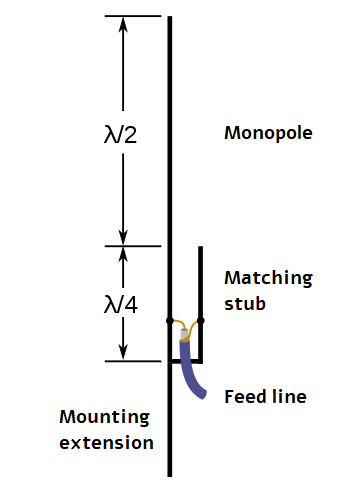 |
| A J-pole antenna |
The matching stub impedance is zero ohms at the closed end and matches
the monopole impedance at the open end. The transmission line, which can
be twin lead or coax, is attached where its impedance matches the stub
impedance. The shield can connect to the short or long tube if fed by
coax.
The J-pole is a popular antenna for amateur radio operators because of its
easy construction and connection. Amateurs often make them from copper
water pipe and fittings. The long side of the antenna usually extends
beyond the bottom of the J to provide a convenient mounting point.
RF Chokes
Some antennas reflect some of the energy they receive from the transmission line. This is a particular problem with end-fed antennas fed with coaxial cable. In that case, some RF energy travels back along the coax shield, causing the transmission line to radiate and causing excessive standing waves in the transmission line. To mitigate this, such systems will use an RF choke to block RF energy from returning down the coax. These RF chokes may be coil of wire or ferrite blocks that surround the cable. Sometimes the cable is made into several loops near the antenna, the loops acting as an RF choke.
Loaded Antennas
As explained above, it takes time for waves of electrical energy to
travel from one end of an antenna to the other. For example, it will take
1 microsecond for a wave of electrical energy to travel from one end of a
150-meter antenna to the other end and back. Therefore, the waves of
electrical energy will travel back and forth along a 150-meter antenna 1
million times every second; the antenna resonates at one megahertz.
However, there is another way to look at this. A longer antenna has more
inductance and capacitance. Therefore, it will resonate at a lower
frequency than a shorter antenna.
From this point of view, it stands to reason that you could get an antenna
to resonate at a lower frequency by increasing its inductance or
capacitance by means other than lengthening the antenna. Typically, longer
antennas are required for lower frequencies. However, you can get a
shorter antenna to work at a lower frequency by increasing its inductance
or capacitance. The most common way of decreasing the resonant frequency
of a short antenna is to add a coil of wire somewhere along the length of
the antenna. This is called loading the antenna. For example, a
1-meter-long antenna should resonate at 150MHz. However, with loading, it
may be made to resonate at a much lower frequency, such as 30MHz, which
should require an antenna that is 5 meters long.
 |
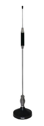 |
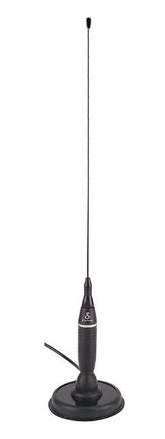
| Base-loaded antenna with magnetic mount. | Center-loaded antenna with magnetic mount. |
 |
 |
| Rubber duckie antenna | Firestik® |
Base loading
A base-loaded antenna is a 1/4 wave antenna with an inductor at the ground-plane end. This is the most logical place for placing the load for mechanical strength. However, this is the area from which most of the electromagnetic energy comes. Since the coil does not radiate much electromagnetic energy, this is the most inefficient loading method. Mobile antennas are often base-loaded to withstand the wind and motion of a moving vehicle.
Center loading
A center-loaded antenna is a 1/4 wave antenna with an inductor around the middle of the antenna. This is more efficient than base loading but puts the weight of the inductor away from the mounting point of the antenna. Therefore, the antenna element may need to be stronger than that for a base-loaded antenna. Sometimes a 1/2 wave antenna may be center loaded. This is essentially two 1/4 wave center-loaded elements butted together to make a single 1/2 wave element. Such center-loaded 1/2 wave antennas are combined into parasitic arrays such as Yagi antennas.
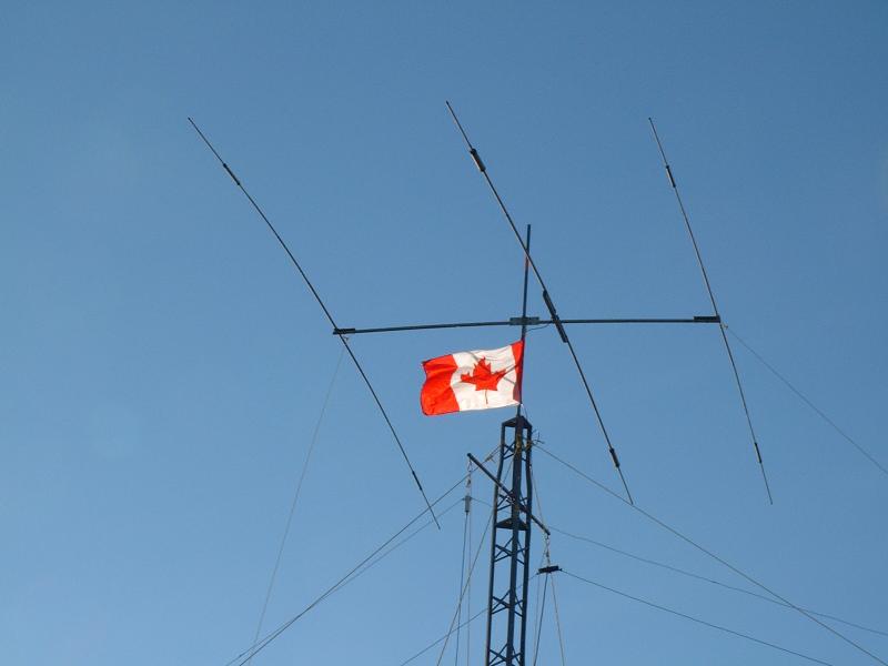 |
| A Center-loaded Yagi antenna |
Tip loading
Tip loading puts the inductor at the tip of the antenna, where it puts the most mechanical stress on the whole antenna element. For this reason, tip loading is not very common, even though it is the most efficient.
Rubber duckie
A "rubber duckie" antenna is a flexible coil of wire that constitutes the entire antenna. Therefore it is a continuously-loaded antenna. It is inefficient but short and very flexible. Rubber duckies are used where their shortness and flexibility are more important than radiation efficiency, such as for hand-held units (handy-talkies/walkie-talkies), especially those used in a rugged environment (law enforcement, fire protection, etc.). Rubber duckies are usually contained inside a flexible rubber tube, giving it a one-piece appearance.
Firestik®
The Firestik® is a brand name for a rigid continuously-loaded antenna. Its construction is similar to a rubber duckie except that the coils are very widely-spaced toward the base of the antenna; with some designs, they are almost straight. The spacing of the coils gets closer toward the tip of the antenna, where the coils are tightly wound. It is, therefore, essentially a tip-loaded antenna. Since the coils are widely-spaced at the base, it is efficient at radiating there, where it needs to be most efficient. The Firestik® has a rigid fiberglass core and is vinyl-coated. It is best known as a CB radio antenna but is available for many bands.
Several manufacturers have made this antenna style since the Firestik® company's patents expired long ago. They are generally called Firestik® because that name made the style famous.
Ferrite loop antenna
A ferrite loop antenna is a coil of wire wound on a ferrite[7] core. The core increases the inductance, making the antenna act as if it were around 1,000 times its physical size. They are typically used as receiving antennas at around 1 MHz and lower frequencies, particularly in the AM broadcast band. They are popular in this application because other antenna types are very large at such frequencies (around 150 meters for a 1/2 wave antenna).
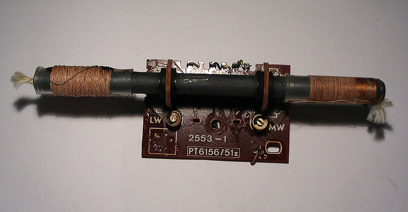 |
| A ferrite loop antenna from an AM radio receiver. |
Helical antenna
The helical antenna may resemble a continuouly loaded antenna in that the entire lenght of the antenna is coiled. However, each turn is one wavelength in diameter and separated from the next by one wavelength. Therefore, it doesn't simply act like a shortened antenna.
|
|
| A helical antenna array used for satellite communication |
A helical antenna radiates strongly along the axis of the loops, and the
waves are circularly polarized. With a reflector at one end, the antenna
radiates strongly in one direction. For this reason, helical antennas are
often used for satellite communication.
The antenna described above is often differentiated as an axial mode
helical antenna. However, if the turns are significantly smaller and
closer together than one wavelength, the antenna acts more like a
continuously loaded antenna. In that case, it is called a normal mode
helical antenna.
Antenna Arrays
Below are some diagrams of the radiation patterns for antenna arrays. To understand what these diagrams are depicting, look at the following diagram.
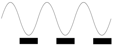 |
| A radio wave represented by sine waves. The radiation diagrams below represent the waves by alternating white and black bars. . |
This shows that the alternating black and white rings in the radiation
diagrams below represent each wave's positive and negative halves.
When the waves interact in phase (peaks together and troughs together),
the energy adds together. The radiation diagrams show this by the white
and black bars lining up directly. When the waves interact out-of-phase
(peaks and troughs alternate), the energy of one wave cancels the energy
of the other. This creates an area where there is no electromagnetic
energy. In the radiation pattern diagrams, the bars alternate. Each line
fills in the space between the other antenna's lines. This shows that the
energy is canceled in this area.
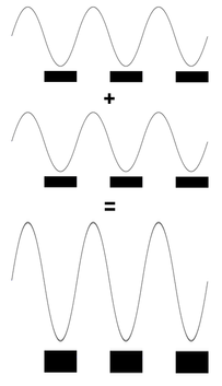 |
| When waves interact in-phase the amplitudes add together. |
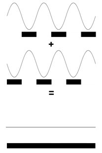 |
| When waves interact out-of-phase, the amplitudes subtract from each other. If the amplitudes are equal, the waves are completely canceled. |
Single antenna
In the following diagram, you are looking down at a single antenna. The waves radiate in concentric rings. There is no interference, and the signal is omnidirectional.
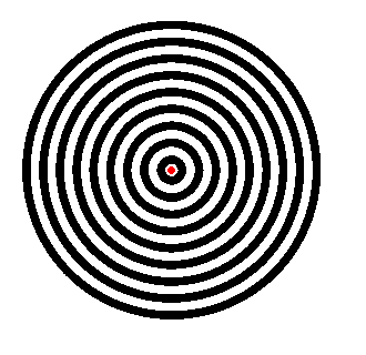 |
| Radiation from a single antenna viewed from above (the red dot represents the antenna). |
Broadside array
The following diagram depicts two antennas 1/2 wavelength apart, arranged left to right. They are fed in phase, so the signal reaches both antennas at the same time. As a result, the waves line up where they meet perpendicular to the array. There, the waves combine their energy to become larger waves. You can see this where white and black arcs alternate (going up and down on the page in the diagram below). However, going left and right, the positive half of one wave lines up with the negative half of the other. This is depicted by the black arcs filling in the white arcs in the diagram. This causes the waves to cancel each other along this line. There are no alternating white and black arcs, showing that the waves are canceled.
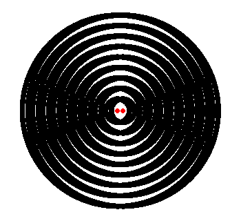 |
| Two antennas that are 1/2 wavelength apart and fed in phase. |
The radiation pattern for a broadside array is much like a horizontal dipole. However, because the antennas are oriented vertically, the waves are vertically polarized.
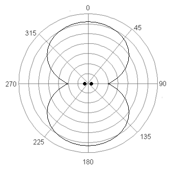 |
| The radiation pattern of a two-element broadside array with the elements lined up left to right. |
Endfire antenna
In the following diagram, the antennas are fed out-of-phase (the positive half of the signal reaches one antenna when the negative half reaches the other). In that case, the radiation is concentrated along the plane of the antenna elements. The radiation is canceled perpendicular to the antenna plane—the radiation pattern is rotated 90 degrees to that of a broadside antenna. You can see this in the following diagram.
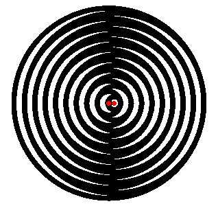 |
| Two antennas that are 1/2 wavelength apart and fed out-of-phase |
The radiation plot for an endfire array is about the same as that for a broadside array, except it is rotated 90 degrees and lines up along the array plane.
Adding antennas to either array increases the effect. For example, the following diagrams show the radiation patterns with four antennas in a line.
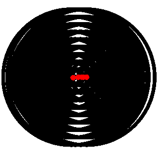 |
| A four element broadside array. The radiation is even more directional. |
Notice that the alternating black and white lines follow a much narrower angle (representing where the energy is radiated). This isillustrated in the radiation pattern plot below.
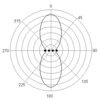 |
| A four element boradside array has a narrower radiation pattern than a two-element array. |
If the elements are fed out of phase, the pattern is likewise concentrated along the plane of the array.
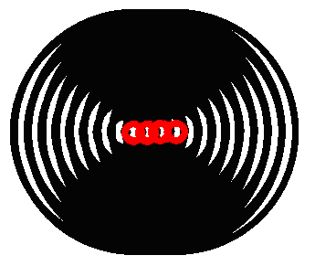 |
| Radiation from a four element endfire array. |
This demonstrates that an antenna array can be made directional by controlling the phase between the individual antennas. The above illustration shows antennas fed in-phase or 180 degrees out-of-phase. If the phasing is somewhere between, the array will radiate at an angle to the alignment axis.
AM broadcasting arrays
AM broadcasting may use single antennas with omnidirectional signals (as described above) or antenna arrays. These arrays are used when licensing requires directing the signal in a specific direction. Antenna arrays may be in-line and operate like the arrays described above. However, the elements are often fed with complex phasing that directs the signal in a more complex pattern. This allows one radio station to cover a particular geographic area without interference from another station. One notable example was KCBQ in the San Diego, California, area. KCBQ operated on 1170 kHz at the maximum allowed 50,000 watts in the daytime and could theoretically cover most of North America. However, the station was required to direct its signal away from Cuba (over 3,000 kilometers away). This protected a Voice of America station directed at the island. KCBQ used a six-element array arranged in two staggered lines of three antennas.
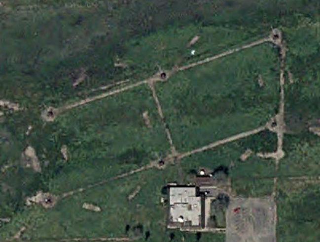 |
| KCBQ's former antenna array. USGS image dated 12/31/2002. |
Another notable aspect of KCBQ is that the station, still operating on 1170 kHz, currently shares an antenna array with KECR, which operates at 920 kHz a few miles east of KCBQ's former location. Two stations operating on different frequencies with different power and radiation pattern requirements use the same antenna array.
Phased arrays
The antennas described above are phased arrays. However, in modern
usage, the term "phased array" is frequently associated with a matrix of
antennas.
A good example of a phased array is the antenna used for early radar
systems. One system used an array of dipole antennas with a metal mesh
reflector. When fed in phase (all antenna elements receiving the signal
simultaneously), the radiation is perpendicular to the plane of the array.
The reflector causes the radiation to go in only one direction instead of
two. The large number of elements in the array causes a very narrow beam
of energy; the antenna is highly directional.
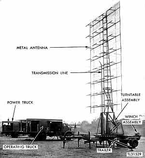 |
| SCR-270 Radar unit like those at Pearl Harbor on Dec. 7, 1941. This is a phased array of dipole antennas with a mesh reflector. |
Early radar systems always fed the antennas in phase, so the antenna was
steered by physically turning the whole array.
Modern phased arrays are often steered electronically by changing the
phasing of the signal. This is achieved by causing the signal to reach the
antennas at different times. Such a delay can be achieved through
different lengths of transmission line. However, the delay is usually
achieved through electronic delay circuits.
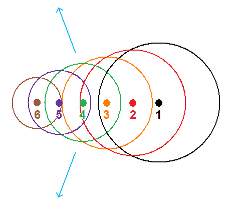 |
| A linear phased array radiates in the directions of the arrows when the feed signal arrives at the rightmost element (element 1, the black dot) first, then each other element in succession. Change the delay between elements and the radiation angle changes. |
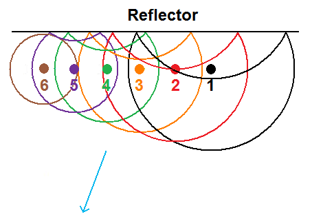 |
| Add a reflector, and all the radiation goes in a single direction. This antenna array can be steered in any direction, from left to right, by simply changing the delay (phase) of the signals. Arrange the antennas on a grid, and you can steer in any direction, left to right and up to down. |
Such electronic steering can be done very rapidly. For example, an electronically-steered phased array radar system can track several targets simultaneously by rapidly steering the antenna from one target to another.
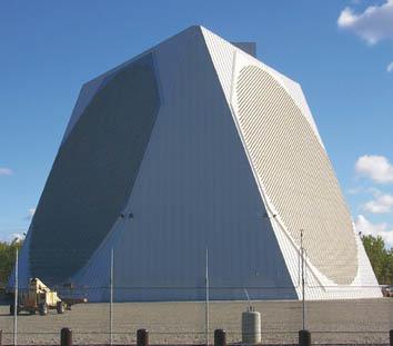 |
| Electronically steered phased-array early warning radar used by NORAD in Alaska. |
The individual elements of a phased array antenna may be dipoles fabricated from metal rods or tubing but can also be made on a printed circuit board or a silicon chip. However, any antenna can be arranged in a phased array.
Beam antennas
Antennas with passive radiators
Yagi
The Yagi or Yagi-Uda (named after its inventors) is similar to a phased
array antenna. It is a dipole antenna with one or more "monopole"
antennas nearby in critical locations. These monopoles are not driven;
they do not receive any energy from the transmission line. They are called
passive or parasitic radiators.
The simplest Yagi antenna is the two-element Yagi. The typical design has
a 0.44 wavelength dipole with a 0.5 wavelength monopole placed 0.25
wavelength from it. In the following diagram, the Greek letter lambda
represents wavelength. Therefore 0.5λ means 1/2
wavelength.
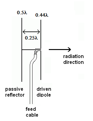 |
| Design of a two-element Yagi |
Radiation from the driven dipole creates currents in the passive monopole. These currents cause the monopole to radiate energy as if it were itself driven. Because the driven dipole is shorter than it should be, it doesn't resonate perfectly. This results in a phase difference between the driven element and the reflector; the elements act as a phased array. The waves interfere destructively, going past the reflector and constructively past the driven element. This effectively reflects the radiation toward the driven element. The following is a radiation pattern plot for a two-element Yagi antenna.
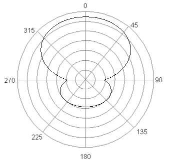 |
| The approximate radiation pattern of a two-element Yagi antenna. |
The Yagi antenna can be made more directional by adding a third element opposite to the reflector. This element will be 0.43 wavelength long and 0.13 wavelength from the driven element.
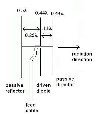 |
| Design of a three-element Yagi antenna. |
The passive element opposite the reflector is called a director.
A Yagi antenna will have only one reflector but can have multiple directors. Increasing the number of directors further concentrates the beam. The following antenna is a four-element Yagi. Next is a five-element Yagi with a folded-dipole driven element.
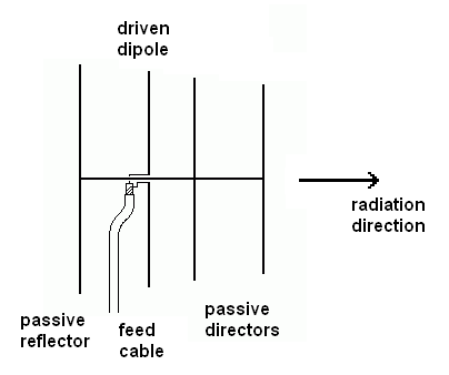 |
| Design of a four-element Yagi. |
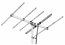 |
| A five-element Yagi TV antenna with a folded dipole driven element. |
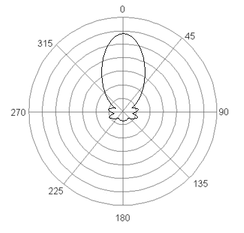 |
| The approximate radiation pattern of a six-element Yagi antenna. Notice the multiple lobes showing that the antenna radiates a bit to the side. Many directional antennas have such off-axis lobes.. |
Two-element Yagi antennas may consist of a driven element and a director without a reflector.
Multiband Yagi antennas have a mix of longer and shorter elements, essentially two antennas built on the same support pole. Yagi TV antennas are usually multiband antennas. For example, a Yagi TV antenna may have a separate UHF antenna at the front, with the main antenna being a mix of long and short elements.
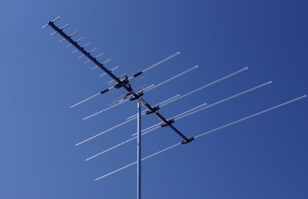 |
| A multiband TV antenna with a dedicated UHF Yagi mounted in front of a dual-band Yagi main antenna.. |
When parasitic radiators are added to a dipole, as with a Yagi, the
impedance drops. A Yagi antenna may have an impedance of as little as 12
ohms. This must be compensated with the matching system.
Yagi antennas may be mounted vertically or horizontally. As with any other
dipole-based antenna, the radio waves transmitted by a Yagi antenna are
the same as the antenna orientation. Therefore, if the transmitting
antenna is mounted vertically, any receiving antennas must be oriented to
receive a vertically polarized signal.
Quad antennas
A quad antenna, sometimes called a cubical quad, is similar to a Yagi antenna, except the driven and passive elements consist of loops instead of dipoles. A quad antenna may be mounted with the sides of the loop vertical and horizontal or on point.
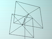 |
| A two-element quad antenna. |
It is beyond the scope of this class to cover the many details of quad antenna design. In short, the advantages over a Yagi antenna are: higher gain, easier to design for multiband use (different sized loops on the same frame), easy to change polarization (horizontal or vertical), higher radiation resistance, they work well lower to the ground, shorter length, and a lower radiation angle.
Antennas with multiple driven elements
Log Periodic antenna
Most antennas only work well at the resonant frequency of the driven
element. A notable exception is the log periodic antenna.
A log periodic antenna is a series of 1/2 wave dipole antennas connected to a
common transmission line. These antennas (elements) operate at
progressively lower frequencies as they progress farther from the first
element. Each element is also fed 180 degrees out of phase with its
neighbors.
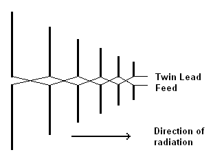 |
| Basic configuration of a log periodic antenna. |
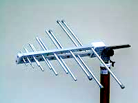 |
| Typical construction of a log periodic antenna. Here the antenna boom is also the feed line with the elements alternating off the two booms. |
Let's look at a three-element log periodic antenna fed at the resonant
frequency of the center element. The center element will resonate with the
signal and develop a high current. This current causes radio waves at the
said frequency. The front element (shorter) and rear element (longer) are
out of phase with the center element, so they will cancel the radiation
from the center element. However, the signal does not reach the front and
rear elements at the same time as the center element due to the distance
it has to travel between them. The final result is that the center element
radiates strongly. The radiation from the front and rear elements are
canceled by the combined radiation of all three elements. Therefore, the
front and rear elements act as passive radiators, the front as a director,
and the rear as a reflector. It is essentially a virtual Yagi antenna.
Now let's feed the antenna at a frequency halfway between the resonant
frequency of the center element and rear elements' resonant frequency. Now
the center and rear elements will interact so that the antenna acts as if
there were a metal element halfway between the elements. At any frequency
between the resonant frequencies of the shortest element and that of the
longest element, the antenna will act as if there were a real metal
element at that frequency. The result is a highly directional antenna that
operates over a wide range of frequencies.
Horn antennas
A horn antenna is a flared waveguide. They gradually transition from the waveguide's impedance to the free space's impedance. Horn antennas may be square, rectangular, or circular in cross-section depending on the waveguide to which they are connected. They are usually small, work at microwave frequencies, and have a wide bandwidth.
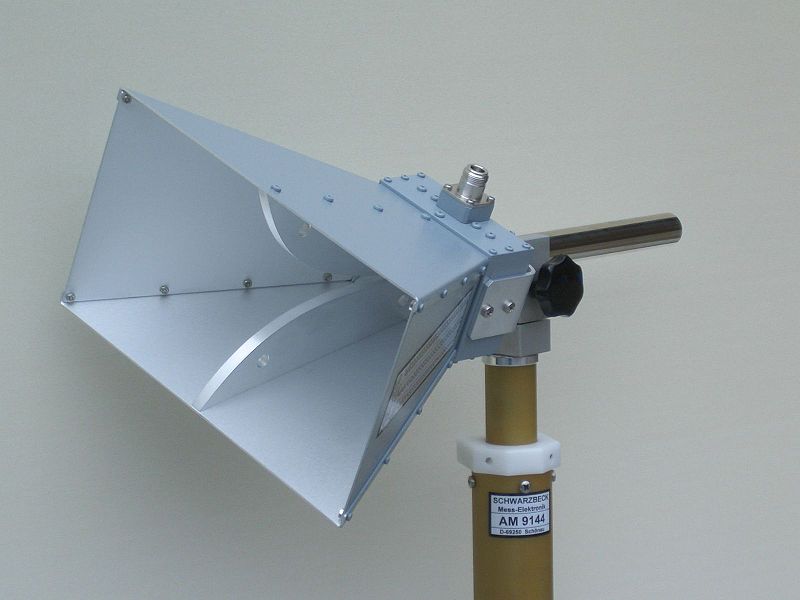 |
| A horn antenna. This one has ridges that increase its bandwidth and operates from 0.8 to 18 GHz.. |
Slot antenna
A slot antenna is essentially a waveguide with slots cut along one side. Each slot acts as a dipole antenna, so a slot antenna works much like a broadside array with a reflector. The slots may be transverse (crosswise) to the length of the waveguide or longitudinal (lengthwise).
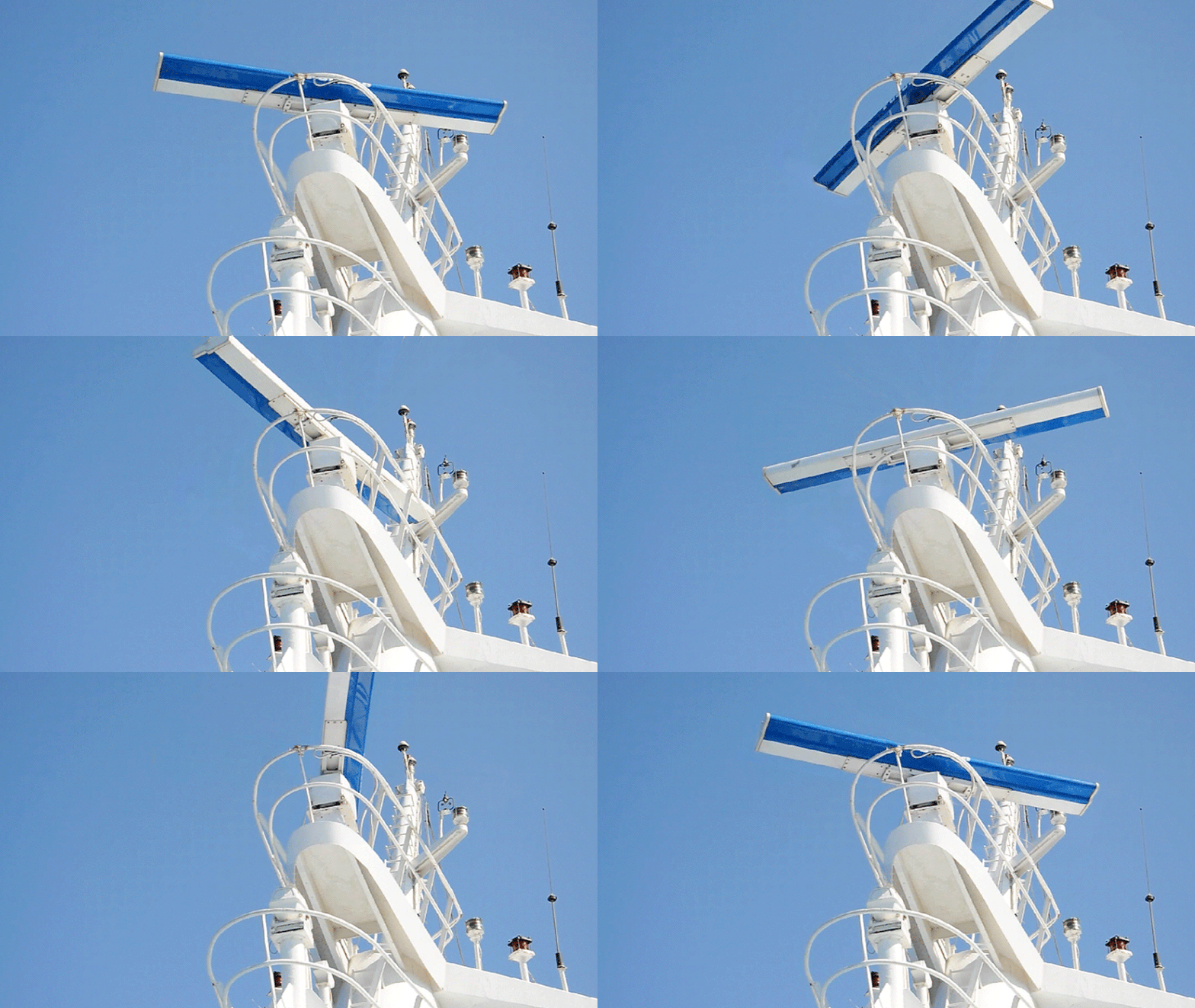 |
| A slot antenna used for a ship's radar. |
Slot antennas often have a V-shaped reflector making the antenna act like a wide horn antenna. This narrows the vertical radiation angle.
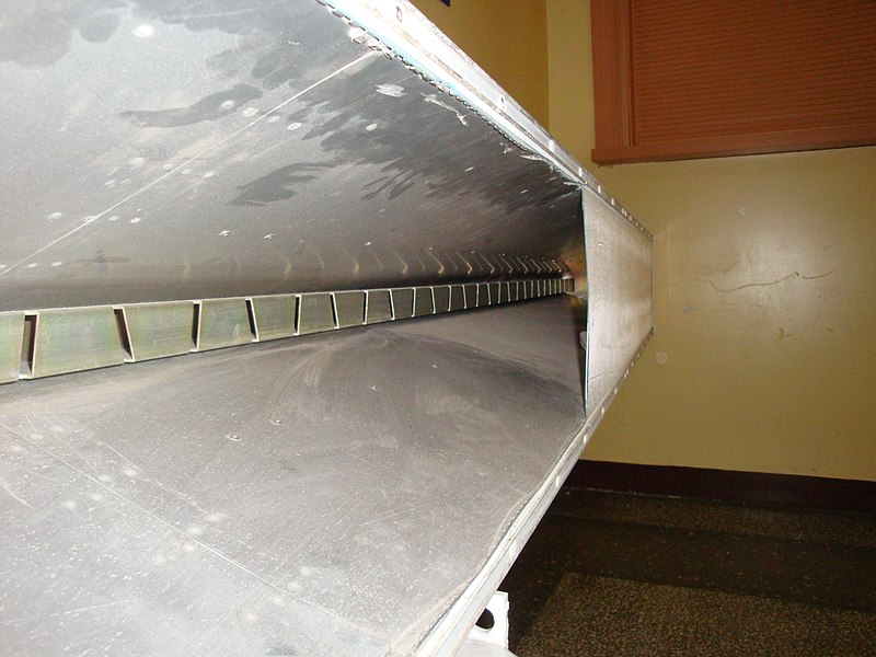 |
| A slot antenna with the plastic cover cut away showing the V-shaped waveguide with the antenna in the center. |
Reflecting Antennas
Corner reflector
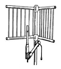 |
| Corner reflector antenna. |
A corner reflector has a reflecting surface that allows a dipole to receive or transmit in one direction. The reflector may be a solid metal sheet or several wires or tubular elements. Some high-frequency Yagi antennas include a corner reflector at the rear.
|
|
| The top antenna is a UHF Yagi with a corner reflector. The bottom antenna is a small bowtie array (stacked bowties) with a flat reflector. |
Parabolic reflector
A parabolic-reflector antenna has a curved reflector that focuses radio waves on a central antenna element, usually a horn antenna. This type of antenna is generally associated with satellite receivers (aka earth stations), radio telescopes, and microwave links.
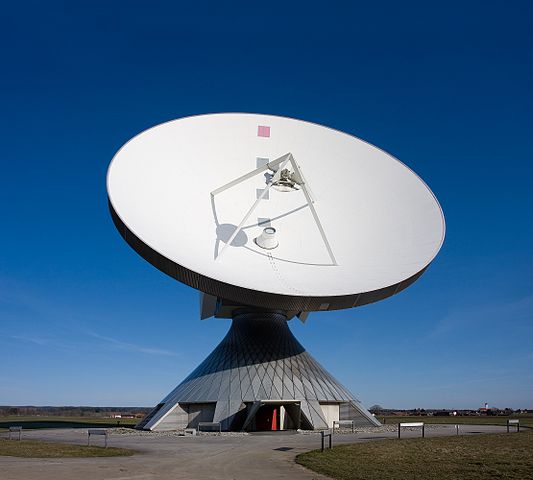 |
| A parabolic satellite-receiving antenna in Germany |
The name "parabolic" comes from the shape of the reflector, which follows a parabolic curve. All points of a wave along the reflector's axis arrive at the focus simultaneously (in phase). If the curve is spherical, some parts of the wave arrive earlier than others, causing some canceling of the energy.[8]
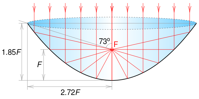 |
| A parabolic reflector. The receiving antenna is placed at the red 'F' (the focus). |
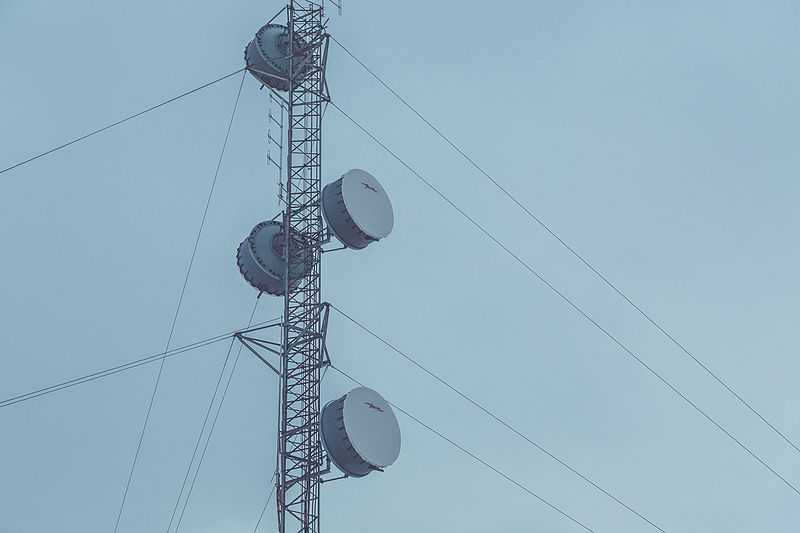 |
| Parabolic microwave link antennas covered for protection from weather, etc[9] |
Of-axis parabolic antennas
An off-axis parabolic reflector is made from a part of the parabolic curve to the side of the central axis. This puts the focus to the side of the incoming radio waves. Home satellite-receiving antennas are often constructed this way.
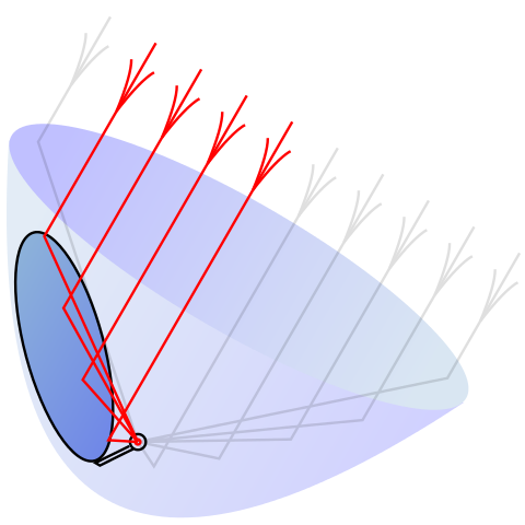 |
| An off-axis parabolic reflector. The physical reflector is made from the darkened part of the parabolic curve in this diagram. This puts the focus to the side of the incoming waves. |
A horn reflector antenna is a combination of an off-axis parabolic reflector and a horn antenna. An off-axis parabolic reflector turns the radio signal 90 degrees into a horn antenna. These are frequently used for cross-country telephone links. The antenna that discovered the cosmic microwave background is a large horn reflector antenna.
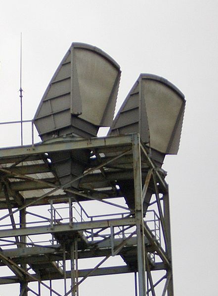 |
| Horn reflector antennas used for microwave links. |
Antenna Masts
Freestanding
A free-standing mast is a tower that has no supporting guy wires. They are sturdy structures, able to withstand the winds or earthquakes they may be subjected to without extra support.
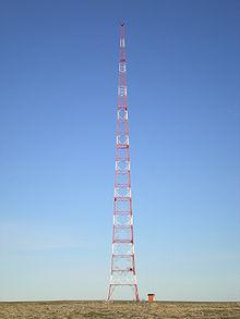 |
| A free-standing antenna mast. |
Free-standing masts are common with lower frequency, longer wavelength transmissions. The typical bands of operation are Very-low Frequency (VLF, 3 to 30 kHz), Low Frequency (LF, 30 to 300 kHz), Medium Frequency (MF, 300 kHz to 3 MHz), and the lower parts of the High-Frequency band (HF, 3 to 30 MHz).
Guyed Towers
Guyed towers are partly supported by guy wires and are less robust than free-standing towers.
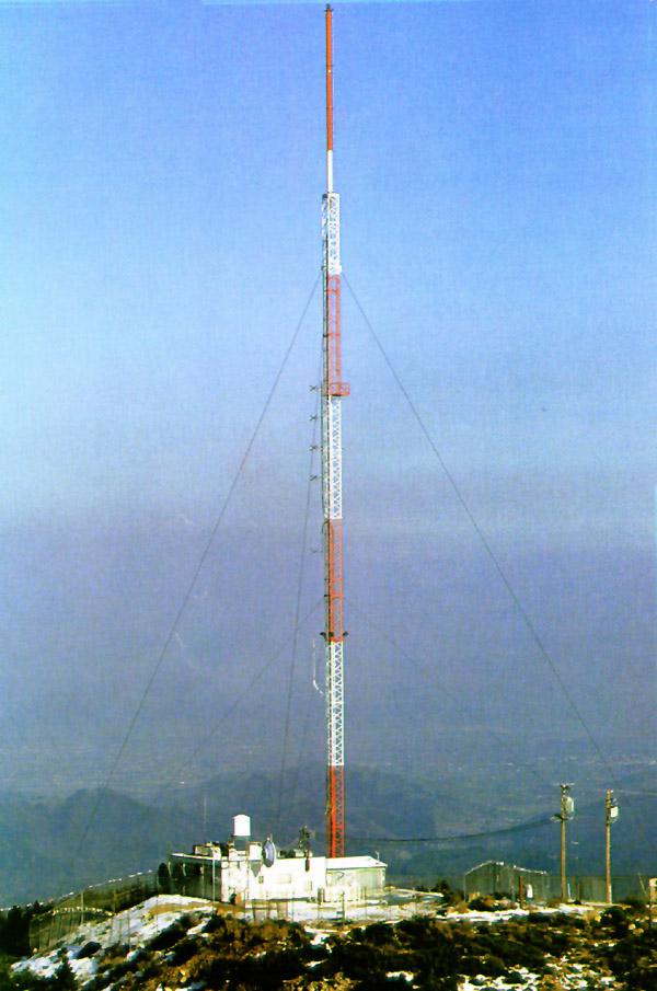 |
| A guyed mast |
With their extra support from guy wires, guyed towers need not be as robust as free-standing towers making them less expensive to build to a given height. However, guyed masts take much more ground space than free-standing towers.
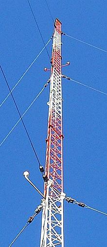 |
| Guy wires attached to the mast. |
Until recently, the tallest man-made structures in the world were guyed
antenna masts. Between 1974 and 1991, the 646-meter-tall (2,121 feet)
Warsaw Radio Mast was the tallest man-made structure in the world. When
the Warsaw Radio Mast collapsed, the record reverted to the previous
owner, the KVLY-TV mast in Blanchard, North Dakota, built-in 1963 at 629
meters (2,063 feet). After that, however, the Warsaw Radio Tower and the
KVLY-TV mast were dwarfed by Burj Khalifa, a skyscraper in Dubai built in
2010, reaching 830 meters (2,722 feet). In 2011, the KVLY-TV mast was
surpassed as the world's second tallest man-made structure by Tokyo
Skytree, a free-standing antenna mast reaching 634 meters (2,080 feet).
The guy wires are made from conductive metal and thus act as passive
radiators. Some guyed antennas take advantage of this, using some guy
wires as a ground plane or as the cone part of a discone antenna. However,
radiation from the guy wires usually needs to be suppressed so it doesn't
change the antenna's radiation pattern. Therefore, guy wires are broken
into segments that are less than 1/5 of the operational wavelength. Guy
wire insulators are used for this purpose.
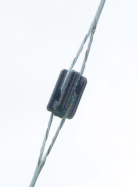 |
| Guy wire insulator |
Mast radiator
A mast radiator is an antenna where the mast is the antenna. To ensure that the entire structure acts as a single electrical conductor, joints between sections are connected electrically by copper jumpers, or the sections are welded together. Unless the design calls for grounding of the base, the base of the mast is insulated from the ground. A mast radiator may have a capacitive "top hat." This is a round horizontal structure at the top of the antenna that increases the antenna's capacitance.
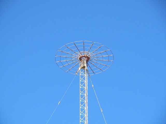
A capacitive "top hat" on the ABC AM radio tower in Hamersley,
Western Australia.
A top hat makes the antenna resonate at a lower frequency
without building the antenna taller. Mast radiators are typically used in
the Very-low Frequency band (VLF, 3 to 30 kHz) to the lower parts of the
High-Frequency band (HF, 3 to 30 MHz). A mast radiator may be a 1/4
wave ground plane antenna. However, they are often end-fed monopoles.
Antenna supported by a mast.
Antennas used for the higher parts of the HF band and above are usually supported by masts rather than being the mast itself. Typical applications are television or FM radio antennas. TV and FM radio antennas are often mounted on top of AM mast radiator antennas.
Dummy Load
You use a dummy load when testing a radio transmitter, and you don't want to broadcast a signal. A dummy load is a resistor with a resistance that matches the impedance of the transmission line. For low power, a dummy load may be no more than a small resistor. However, large high-wattage resistors, sometimes with large heat sinks, are needed for high power. A popular dummy load is called the "Cantenna." A large resistor is inside a one-gallon paint can filled with cooling oil. In professional installations, a dummy load may be a large water-cooled resistor system.
|
|
| A "Cantenna" dummy load used for amateur radio |
|
|
| A 100 kW dummy load that uses a sodium hydroxide coolant at the Moosbrunn short wave transmitting comples in Moosbrunn, Austria. |
Safety
Lightning
Needless to say, tall antennas are lightning magnets. Antenna masts are connected to the earth by heavy-gauge wires. Connections to ground wires must not be soldered but bolted or welded. Mast radiators that cannot be grounded during normal operation may have a grounded metal bar near the base. This acts as a spark gap. If lightning strikes the antenna, the voltage will ionize the air between the antenna and the bar. As a result, the current jumps the gap to ground rather than taking a destructive path. Small installations often have lightning arresters on the transmission lines. These are spark gap devices that connect along the transmission line. Some lightning arresting devices use a gas-filled tube instead of a spark gap. This offers protection from weaker lightning strikes that may not jump a spark gap yet have enough energy to cause damage.
Power lines
Installing an antenna mast near power lines is an obvious danger. Care must be taken to ensure a mast is not raised into power lines or allowed to fall on power lines. If an antenna mast falls, snapping guy wires can fly into nearby power lines. You don't actually need to touch high-voltage power lines to be electrocuted. Electricity will jump up to about 3.5 meters (11 feet) from 500 kV power lines.
Electromagnetic radiation
Some high-power installations emit dangerous levels of electromagnetic radiation. You will find warning signs around such installations. Where warning signs are impractical (as with some military aircraft), operators are trained to turn off the equipment when people may come in the path of the radiation.
High voltage
High-power installations may have high voltages along the antenna or transmission lines. Even if such voltage isn't high enough to be dangerous, it may cause undesirable effects, such as arcing between wires, etc. Commercial AM broadcast antennas and lower frequency installations are often end-fed monopoles. Due to the high impedance, high voltages are required to feed such antennas. Such high-powered stations have dangerous voltages at the base of the antennas.
.
Antennas - Answers to Questions
| Vocademy |