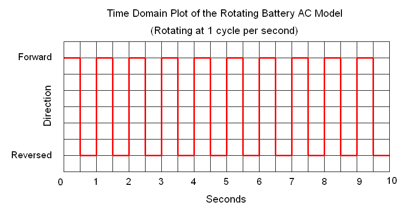
The "Forward" and
"Reversed" labels can be replaced with "Positive" and "Negative"
labels. Here the reversals are abrupt, as in flipping a switch back and
forth. Other AC waveforms make smooth changes such as a sine wave
(described below). There can be other patterns too as we will see below.
The AC delivered by the power grid is in the form of a sine wave. This
is the
natural result of rotating a magnetic field past coils of wire.
AC is also created by electronic oscillator circuits. Theses
produce AC waves of low power for various circuits such as sound
generators, radio circuits and digital circuits. Function generators use
oscillators to produce a variety of low power wave shapes for
testing purposes. The usual waveforms available from a function
generator are a sine wave, a triangle wave (which appears as repeated
isosceles triangles in a graph) or a square wave (the time
domain graph of the rotating battery above is a square wave). These
waveforms
each have certain characteristics that make them suitable for testing
circuits. Another useful waveform is the sawtooth wave (the time domain
plot of the clock hands in
The Time
Domain is a sawtooth wave). These
are all
described below.
The Sine Wave
A sine wave makes a smooth transition as it reverses direction and is
the most pure waveform possible. In fact, all other waveforms can be
broken down into separate sine waves. A sine wave is mathematically
related to a circle. Because of this, some of the same nomenclature
used to describe and measure circles is also used for sine waves.
Rotating Disk Model
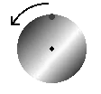
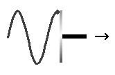
One way to envision a sine wave is by
imagining a spot on a rotating disk. Looking at the disk face-on the
spot will move in a circle. Looking at the disk edge-on the spot will
move up and down. If the disk is then moved uniformly along the
rotational axis the spot will trace a sine wave. Another way to
describe it is that a sine wave looks like a spiral seen edge-on.
There is a close relationship between the time domain graph of the
angle of the clock hands and a sine wave. This graph showed the change
in angle over time. If the graph is made with the trigonometrical sine
of the angle instead of the angle in degrees, it would appear as a sine
wave.
Parameters
There are four parameters used to measure sine waves: amplitude, phase,
frequency and period.
Amplitude
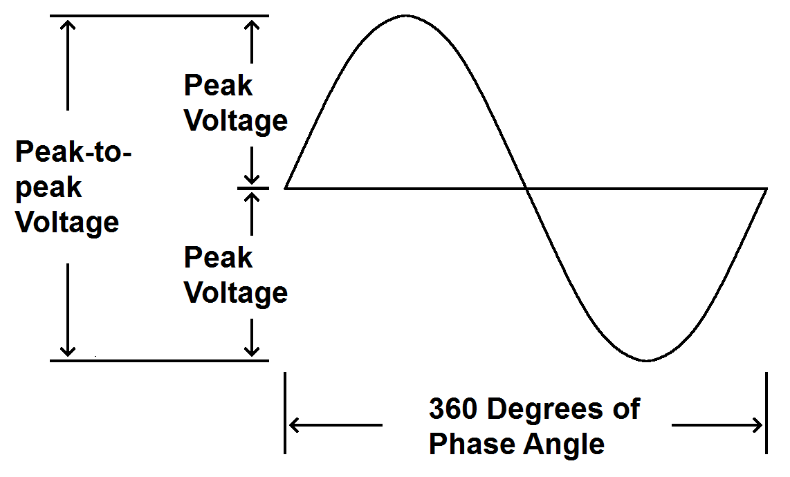
Amplitude represents how large the wave is. Amplitude can be any
appropriate measurement (volts, amperes, watts, etc.). Amplitude
is expressed in three different ways: Peak, peak-to-peak and RMS. The
RMS value is not shown in the
above diagram because it is a mathematical construct and can't be
illustrated.
Peak Voltage
Peak voltage is the Maximum deviation from the middle of the wave in
either direction.
Peak-to-Peak Voltage
Peak-to-peak voltage is the maximum voltage from one peak to the
opposite peak, positive and negative. The peak-to-peak voltage is
always twice the peak voltage.
RMS Voltage
RMS (Root-Mean-Square) is a complex calculation that represents
the DC voltage that would dissipate the same power as the AC
voltage being measured. The calculation is made by sampling many
voltages at even
intervals during one cycle. The square-root is taken of each of these
voltages. The arithmetic mean (the average) is calculated for the
square-roots. Finally, this result is squared. This may sound a bit
daunting but for sine waves (and only sine waves) the RMS voltage is
simply 70.7% of the peak voltage. We rarely need the RMS value of other
wave shapes. Most volt meters get the RMS value of an AC wave by
sampling the peak voltage and use a voltage divider to present 70.7% of
that peak voltage. If you do need the RMS value of something other than
a sine wave you will use a "true RMS" volt meter.
Phase
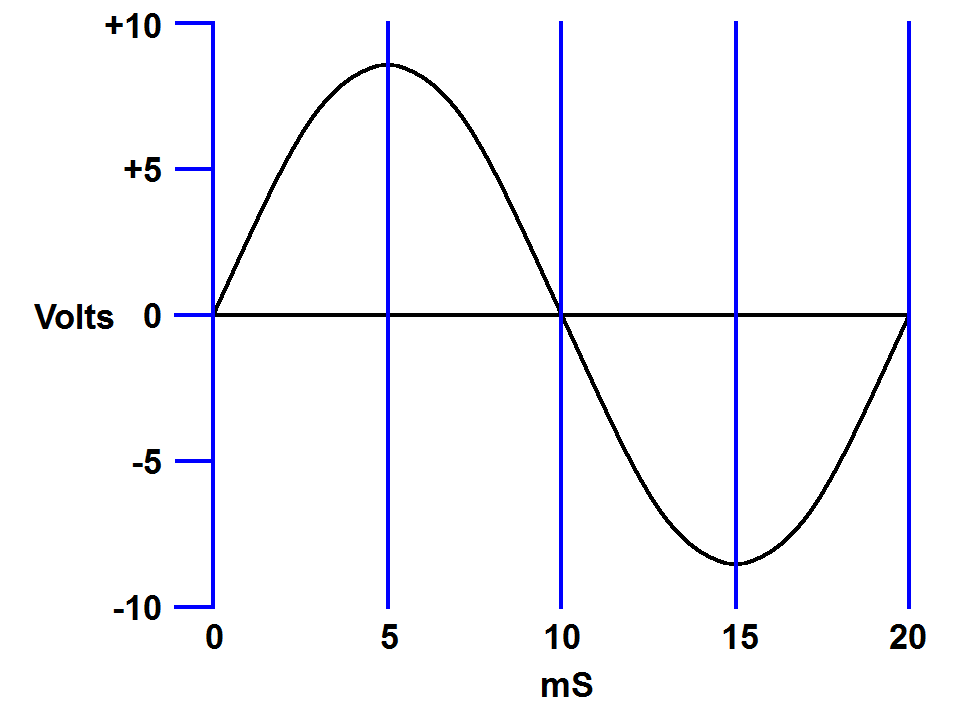
Let's take a look at a sine wave as it looks on an oscilloscope. The
oscilloscope makes a graph of the voltage changes over time. In the image
below, we see a wave with a period of 20 mS (which is a frequency of 50 Hz)
and a peak voltage of about eight volts.
 |
| A 50 Hz sine wave with a peak voltage of
about 8 volts. |
We have drawn this graph so that the wave is at 0 volts at 0
milliseconds. This is arbitrary, but where most people like to start. Now
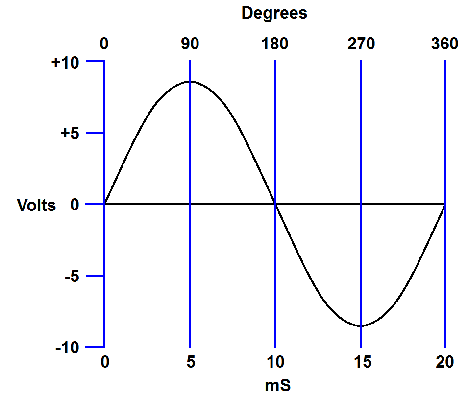
let's add a degree scale with 0 degrees lined up with 0 mS. Again this is
arbitrary, but how most people line these parameters up.
 |
| Sine wave with degree scale |
We have set up our graph so that the wave starts with 0 volts at 0
degrees. The wave peaks at 90 degrees, crosses 0 volts again at 180 degrees,
reaches its negative peak at 270 degrees then starts over at 360 degrees.
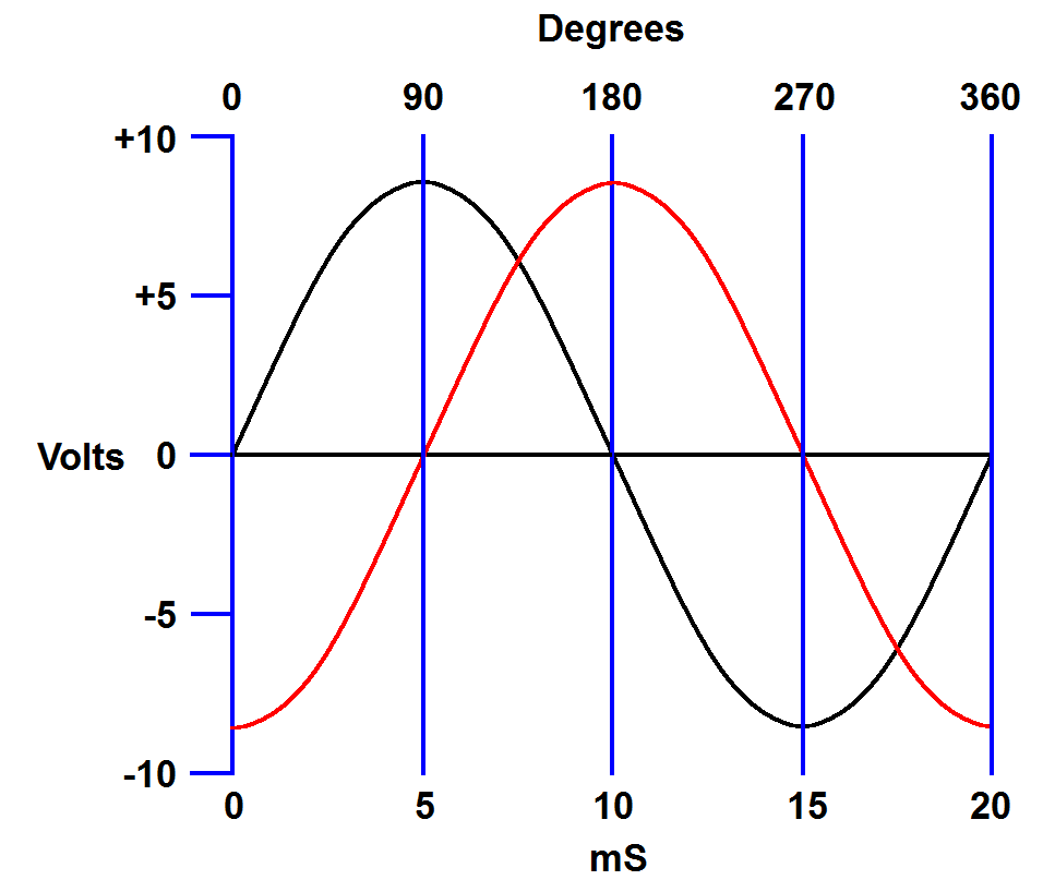
Now let's add an identical wave, except lets have this one cross 0 volts 5
mS after the first wave.
 |
| Two sine waves 90-degrees out of phase. |
Notice that every event of the second wave (red) occurs 90 degrees after
the same event of the first wave. In this case that is also 5 mS later, but
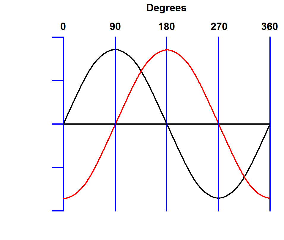
that is only for this particular set of waves. If we remove the time and
voltage scales we see that the waves are still 90-degrees out-of-phase even
if we don't know the voltage or frequency.
 |
| Two sine waves 90-degrees out of phase. |
Here we have demonstrated how the term "phase" is used to compare two
waves of the same frequency that happen at different times. The waves don't
have to be the same amplitude. If they are different amplitudes one is just
larger than the other. The phase relationship doesn't change.
Each
cycle of a wave has 360 degrees and you have a different voltage at each
point. The term phase may be used to specify a particular point along a
wave, but is usually used when comparing one wave to another.
Frequency
Frequency is the number of times the wave completes one cycle in one
second.
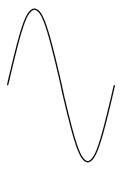
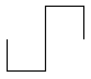
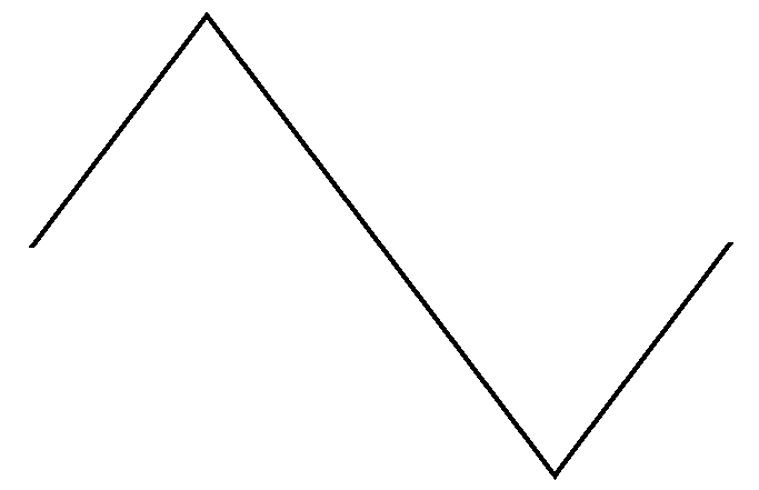
Complete cycles of a sine wave,
a square wave (explained below) and a triangle wave (also explained
below).
|
The above illustration shows one cycle of a sine wave, a square wave
and a triangle wave. These are repeated over and over with alternating
current. If you count how many times a wave repeats every second you
have its frequency. Frequency is measured in Hertz (Hz) where 1 Hz
equals one cycle per
second, 20 Hz equals 20 cycles per second, etc. When we think of AC we
usually think of the power coming from the power grid, such as that
from a wall plug. The frequency here will be 50 Hz or 60 Hz depending
on your location (more about that in power distribution). In electronic
circuits you may have frequencies anywhere in a tremendous range. Audio
frequencies (humans can hear vibrations in the air at audio
frequencies) range from 20 Hz to 20,000 Hz (20 kHz).
Ultrasonic frequencies
(humans cannot hear vibrations in the air at ultrasonic frequencies) range from 20 kHz and
above. Radio frequencies are those
frequencies that are typically used for radio systems. These
frequencies range anywhere from around 50 kHz (and overlap with
ultrasonic frequencies) to billions of cycles per second.
Period
The period of a wave is the time it takes to complete one cycle. The
illustrations below show two sine waves of different frequencies.
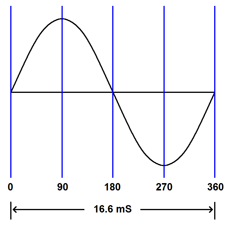
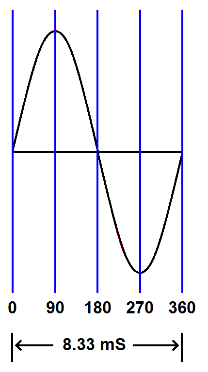
Notice that the 120 Hz wave completes its cycle in half the time of the
60 Hz wave. The 60 Hz wave has a period of 0.0166 seconds (16.6 mS) and
the 120 Hz wave has a period of 0.00833 seconds (8.33 mS). Notice that
higher frequencies have shorter periods.
60 Hz
|
|
120 Hz
|
| The
60 Hz sine wave on the left takes twice the time to complete one
cycle as the 120 Hz sine wave on the right (16.6 milliseconds compared
to 8.33 milliseconds). |
Mathematically the period is the reciprocal of the
frequency and the frequency is the reciprocal of the period. For
example, a 60 Hz wave has a period of 16.6 ms (1
÷ 60 = 0.0166). Calculating
frequency and period by reciprocals will be discussed later along with
using the oscilloscope.
Wave Components
Square waves
Simply switching between two voltages (like turning a switch on and
off) will produce a square wave. It is called a square wave because of
the sharp, square edges when seen on a time domain graph.
A time domain graph of a square
wave
|
A square wave is easy to produce and may look simpler than a sine wave.
Actually, a square wave is much more complex. It turns out that a
square wave consists of a sine wave at the fundamental frequency of the
wave plus all of the odd harmonics (harmonics are multiples of the
fundamental frequency). For example 1 kHz square wave consists of a
sine wave at 1 kHz. It also contains another sine wave at 3 kHz (the
third harmonic), but of a smaller amplitude. It contains yet another
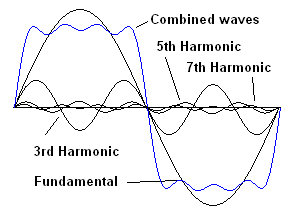
sine wave at 5 kHz of yet smaller amplitude and so on. The following
diagrams show the development of a square wave, starting with a sine
wave and adding odd harmonics (watch the video at the bottom of this page to see various wave shapes built from sine waves).
|
|
|
|
|
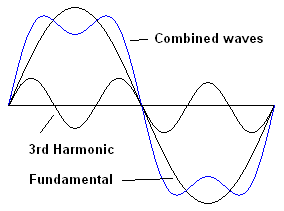
| Here we have a sine
wave of a particular frequency (the fundamental). If we mix in another
sine wave at three times the fundamental frequency (the third harmonic)
they combine to make the blue wave. The sides of the resulting wave are
steeper and the top is pulled down. |
|
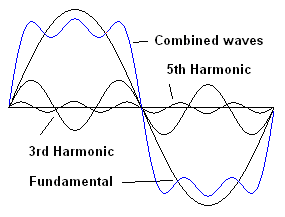
Adding the
fifth harmonic steepens the sides more and starts to flatten the top |
|
Adding the
seventh harmonic steepens the sides even more and flattens the top more. |
If this process is continued, adding higher and higher harmonics, the
wave becomes completely square. This shows how a square wave can be
built by adding sine waves together. Square waves are useful for
testing the bandwidth of circuits, i.e., testing if a circuit can pass
a wide range of frequencies. A circuit with a wide bandwidth will pass
a square wave undistorted. However, if the square wave comes out with a
steep leading edge but a distorted trailing edge, the circuit can't
handle the lower frequencies. If the square wave comes out with a steep
trailing edge and a distorted leading edge, the circuit can't handle
the higher frequencies.
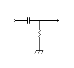
The following example shows a circuit called a high-pass filter. It is
designed to pass high frequencies but block low frequencies. In this
case, the distorted square wave at the output (with a steep leading
edge and a distorted trailing edge) shows that it is blocking low
frequencies.

|
 |

|

|
Square
Wave
|
High-pass
Filter
|
Distortion
due to insufficient low frequency response.
The diagram to the right has
worse low frequency
responese. |
Triangle wave
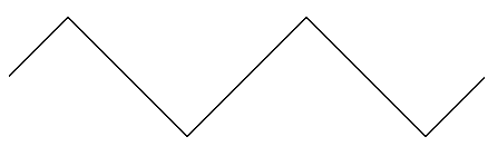
Another wave shape you may encounter is a triangle wave. A triangle
wave has symmetrical linear slopes leading to a peak as shown in the
following diagram.
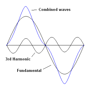
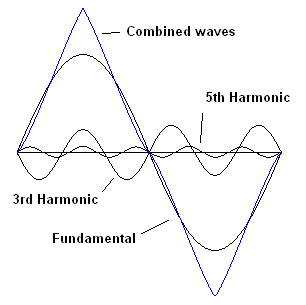
Like the square wave, a triangle wave is made up from the fundamental
wave and all of the odd harmonics. However, each harmonic is 180
degrees out-of-phase (inverted) with the previous one.
|
|
|
Here
the third harmonic is 180 degrees out of phase with the fundamental.
The sides of the combined waves are made less steep and the top
is heightened.
|
|
The
fifth harmonic is back in phase with the fundamental. It steepens the
sides and the top is heightened
even more. The wave is already a triangle wave with little distortion.
Adding more odd harmonics makes the sides straighter.
|
Sawtooth wave
A sawtooth wave is a triangle wave where the slopes are not
symmetrical, i.e. one slope is steeper than
the other. Sawtooth waves were used in
CRT-based televisions and computer monitors to control the movement of
the scanning electron beam. For example, a sawtooth wave that rises
slowly and drops quickly is used to move the electron beam slowly from
left to right then quickly from back to the left.
A sawtooth wave is made up from the fundamental and all of the
harmonics (both odd and even) where each harmonic is 180 degrees out of
phase with the previous harmonic.


