| Vocademy |
Power Distribution
Incandescent lights, fluorescent
lights and AC motors work directly with AC. However televisions, audio
systems, computers, LED lights, battery chargers, etc., must convert
the AC from the power grid to DC. Incandescent lights don't care
whether they have AC or DC. Fluorescent lights and motors can be made
to work on DC. This raises the question, why is power delivered as AC
instead of
DC? This was a matter of quite a debate between Thomas Edison and
George Westinghouse
over how power should be distributed to consumers. Edison advocated DC
where Westinghouse advocated AC. Historians call this
The Battle of the Currents.
Electricity must be delivered at a reasonably low voltage to be safe. However, sending electricity over long distances is much more efficient at high voltages. This is because the commodity we need to get from generating stations to the consumer is power. Electrical energy is converted to power when it turns motors, when light bulbs or radio transmitters convert it to electromagnetic waves or heat and when audio amplifiers create sound waves as they move the air.
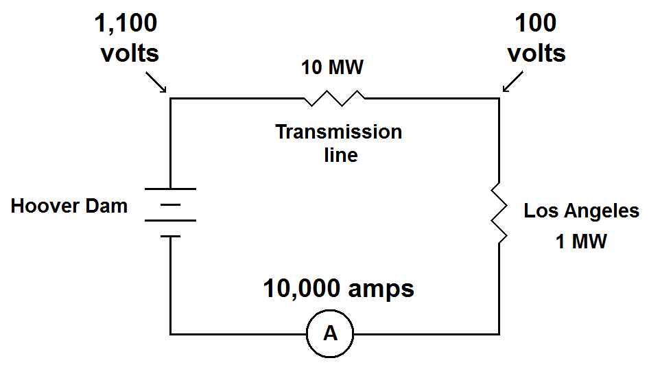
Power is the product of voltage and current. To deliver 1,000,000 watts of power (1 MW) at 100 volts requires 10,000 amperes of current. Imagine what it would take to deliver 1 MW at 100 volts from Hoover Dam to Los Angeles. A copper wire with a diameter of approximately 70 mm can safely carry about 10,000 amperes. A wire with such a diameter stretching from Hoover Dam to Los Angeles would have about 0.1 ohm of resistance. To get a current of 10,000 amperes through 0.1 ohm will require 1,000 volts. The following diagram illustrates this with Kirchhoff's Voltage Law. We need 100 volts at Los Angeles. We are going to need 1,000 volts just to get the current from Hoover Dam to Los Angeles. We need to start out with 1,100 volts have 100 volts left over for Los Angeles. Now we are passing 10,000 amps through a wire that has 0.1 ohm of resistance. Calculating the power using P_=_I2R we find that this wire is dissipating 10 MW of power. We are wasting 10 MW of power heating the desert air along the trip. The generators at Hoover Dam would have to send 11 MW into the wire to have 1 MW left by the time the electricity reaches Los Angeles. The losses exceed the power delivered by a factor of 10.
Imagine the same scenario but this time use a transformer to step the voltage up to 500 kV (500,000 volts). To send 1 MW at 500 kV requires only 2 amperes of current. Using the same 70mm-diameter wire for the same distance (with a resistance of 0.1 ohm) there would be a loss of only 200 mV (0.2 volts) over the entire distance. The power loss would be only 400_mW (0.4 watts). As you can see, the losses are miniscule. If we cut the diameter of the wire in half, saving approximately 75% in the cost of wire the power loss would still be less than 1 watt.
Using AC it is possible to use transformers to step voltages up for delivery over long distances then step them back down again to be used by the consumer. Transformers used for power distribution have losses of only about 1% to 2%. Using Edison's proposed system of low voltage DC, the losses would be so great that generating stations would have to be placed close together throughout the city. DC cannot be stepped up and down by transformers as AC can. Therefore, it would be impossible to deliver electricity over long distances, like from Niagara Falls where it can be produced inexpensively to New York City, as we routinely do today.
When transmitting AC over the power grid there are losses due to the capacitance and electro-magnetic coupling between the wires and between the wires and the ground. Over very long distances these losses become significant. In this case it is economical to rectify the high voltage AC and send the power as high voltage DC. At the destination an inverter turns the high voltage DC into AC to connect it to the rest of the grid. High voltage DC may be sent over two wires (positive and negative) or over a single wire with the Earth as a return path. The Pacific DC Intertie (shown below) carries 3.1 GW at 500 kV DC from The Dalles, Oregon to Sylmar, CA. This link carries nearly 50% of Los Angeles' peak power demand.
Three coils (called stator coils) are placed around a rotating magnet. These coils are placed 120 degrees apart around the housing. As the magnet spins it produces an AC sine wave in each coil.[1]. The voltages produces by the coils are 120 degrees out of phase with each other. A three phase alternator needs three wires to carry the electricity to its destination. Electricians call the wires themselves phases.
Three phase power is designed for industrial motors. If a motor is run with single-phase power much of the time the voltage is at or near zero volts. This leaves the motor coasting or with little impetus much of the time. With three phase power, the motor is wound much like the alternator, with three windings. As the voltage to one winding drops the voltage to the next winding is peaking. The three phases combine in such a way that the power delivered to the motor is constant throughout its entire rotation.
With a wye winding the voltages all cancel at the central point where the coils are connected together. This becomes the zero-voltage reference and is called the neutral connection or neutral wire. The main advantage of the wye winding is the availability of the neutral connection.
Do not confuse the neutral connection with ground. The ground wire is connected to the earth and only carries current when something goes wrong. The neutral wire carries current in normal operation. Even though the neutral wire should be the same potential as an earth ground, wiring faults may cause it to have dangerous voltages. The neutral wire is often connected to the ground wire. It this case, a wiring fault will probably send current to ground and trip the circuit breaker. If the neutral wire is not connected to ground, such faults may not be detected, placing dangerous voltages on the neutral wire.
The other main type of transformer or motor winding is the delta winding. In a delta winding the three coils are connected in a triangle arrangement.
The delta winding has no neutral connection so it is not used where a neutral connection is needed. The delta winding has the advantage of suppressing the third harmonic of the line frequency so it delivers a cleaner sine wave than the wye winding.
Power distribution transformers rarely have both the primary and secondary windings of the same configuration. Typically, at the power station transformers have wye windings connected to wye-wound alternators. The transformer secondary windings are delta-wound and feed current into the power grid over three wires.
When the voltage is stepped back down for the consumer, the transformer often has a delta-wound primary and a wye-wound secondary to create a neutral connection. However, there may also be a delta winding connected to the secondary to suppress the third harmonic and deliver a cleaner sine wave.
Most texts say that connecting to two 120 phases gives you 240 volts. To avoid confusion we will use the same convention here.
Question:
Circuit breakers connect to the incoming power and deliver it to several circuits in the building. Circuit breakers for 120 volt circuits will connect to only one of the 120 volt phases. To balance usage, half of the circuit breakers are connected to one of the 120 volt phases and the other half will connect to the other 120 volt phase. The wire that is connected through the circuit breaker to a phase is now called a "hot" wire. In the U.S this wire is black.
With the circuit breaker box design shown in the left diagram above, the design of the circuit breaker determines which of the two 120 volt phases will be connected to the breaker. Both types of circuit breaker connect to the neutral wire. An electrician would have to be sure to balance the types of breakers used to balance the load. Such a breaker box will usually have one column of breakers. Each circuit breaker has a "hot" and a neutral wire in this type of box. For a 240 volt circuit a special circuit breaker is used that connects to both phases and not to the neutral bus. Another type of breaker box uses smaller breakers in two columns. In this case the circuit breakers are identical to each other but the electrician would equally fill each column. If a 240 volt circuit is needed a special 240 volt circuit breaker is used that connects to both 120 volt phases. Connecting to both 120 volt phases provides a 240 volt circuit. In modern wiring there is also a block connected to a true-earth ground with at least one ground wire fore each circuit. Each circuit will be connected to a number of light switches and wall sockets. You will find that approximately half of you light switches and wall sockets are connected to one phase and the other half to the other phase.
A typical 120 volt circuit handles 15 amperes and a 240 volt circuit handles 30 amperes. High-power appliances that need a 240 supply. Remember that power is the product of voltage and current. If you double the voltage and current, you quadruple the power. Some newer installations, particularly in office areas, have 20 ampere circuits. 20 ampere circuits can be identified by the wall plug, where the long contact (the neutral contact) it "T"-shaped.
Electricity must be delivered at a reasonably low voltage to be safe. However, sending electricity over long distances is much more efficient at high voltages. This is because the commodity we need to get from generating stations to the consumer is power. Electrical energy is converted to power when it turns motors, when light bulbs or radio transmitters convert it to electromagnetic waves or heat and when audio amplifiers create sound waves as they move the air.
Power is the product of voltage and current. To deliver 1,000,000 watts of power (1 MW) at 100 volts requires 10,000 amperes of current. Imagine what it would take to deliver 1 MW at 100 volts from Hoover Dam to Los Angeles. A copper wire with a diameter of approximately 70 mm can safely carry about 10,000 amperes. A wire with such a diameter stretching from Hoover Dam to Los Angeles would have about 0.1 ohm of resistance. To get a current of 10,000 amperes through 0.1 ohm will require 1,000 volts. The following diagram illustrates this with Kirchhoff's Voltage Law. We need 100 volts at Los Angeles. We are going to need 1,000 volts just to get the current from Hoover Dam to Los Angeles. We need to start out with 1,100 volts have 100 volts left over for Los Angeles. Now we are passing 10,000 amps through a wire that has 0.1 ohm of resistance. Calculating the power using P_=_I2R we find that this wire is dissipating 10 MW of power. We are wasting 10 MW of power heating the desert air along the trip. The generators at Hoover Dam would have to send 11 MW into the wire to have 1 MW left by the time the electricity reaches Los Angeles. The losses exceed the power delivered by a factor of 10.
|
Using DC to deliver 1 MW at 100 volts from Hoover Dam to Los Angeles would lose 10 MW along the way. |
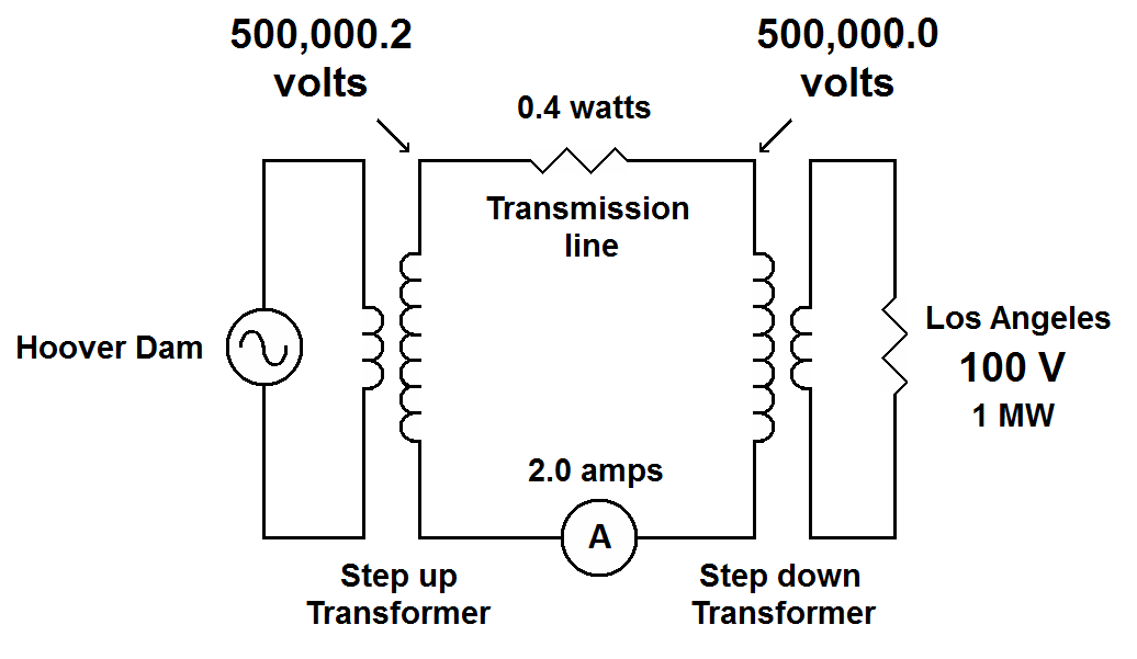
Imagine the same scenario but this time use a transformer to step the voltage up to 500 kV (500,000 volts). To send 1 MW at 500 kV requires only 2 amperes of current. Using the same 70mm-diameter wire for the same distance (with a resistance of 0.1 ohm) there would be a loss of only 200 mV (0.2 volts) over the entire distance. The power loss would be only 400_mW (0.4 watts). As you can see, the losses are miniscule. If we cut the diameter of the wire in half, saving approximately 75% in the cost of wire the power loss would still be less than 1 watt.
|
Using
AC the voltage can be stepped up to 500 kV. At this voltage the losses
are insignificant. The voltage is stepped back down to deliver 100
volts to Los Angeles. |
Using AC it is possible to use transformers to step voltages up for delivery over long distances then step them back down again to be used by the consumer. Transformers used for power distribution have losses of only about 1% to 2%. Using Edison's proposed system of low voltage DC, the losses would be so great that generating stations would have to be placed close together throughout the city. DC cannot be stepped up and down by transformers as AC can. Therefore, it would be impossible to deliver electricity over long distances, like from Niagara Falls where it can be produced inexpensively to New York City, as we routinely do today.
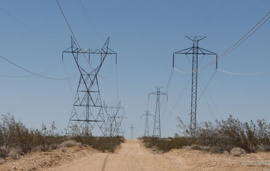
When transmitting AC over the power grid there are losses due to the capacitance and electro-magnetic coupling between the wires and between the wires and the ground. Over very long distances these losses become significant. In this case it is economical to rectify the high voltage AC and send the power as high voltage DC. At the destination an inverter turns the high voltage DC into AC to connect it to the rest of the grid. High voltage DC may be sent over two wires (positive and negative) or over a single wire with the Earth as a return path. The Pacific DC Intertie (shown below) carries 3.1 GW at 500 kV DC from The Dalles, Oregon to Sylmar, CA. This link carries nearly 50% of Los Angeles' peak power demand.
|
Power
lines in the Mojave Desert along State Route 14 near Ridgecrest,
California. To the left is a typical 500 kV three phase AC transmission
line. To the right is the 500 kV Pacific DC Intertie (note the two sets
of conductors identifying this as a DC power line).
Notice in the
following video, Modern Marvels - High Voltage, that the electrical
workers are working on the Pacific DC Intertie. |
Three phase power
In a power plant, electricity is produced by three phase generators. They are often called alternators because they produce alternating current. The following illustration shows a simplified model of a three phase alternator.|
A three phase alternator. |
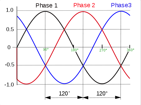
Three coils (called stator coils) are placed around a rotating magnet. These coils are placed 120 degrees apart around the housing. As the magnet spins it produces an AC sine wave in each coil.[1]. The voltages produces by the coils are 120 degrees out of phase with each other. A three phase alternator needs three wires to carry the electricity to its destination. Electricians call the wires themselves phases.
|
Output of a three phase alternator |
Three phase power is designed for industrial motors. If a motor is run with single-phase power much of the time the voltage is at or near zero volts. This leaves the motor coasting or with little impetus much of the time. With three phase power, the motor is wound much like the alternator, with three windings. As the voltage to one winding drops the voltage to the next winding is peaking. The three phases combine in such a way that the power delivered to the motor is constant throughout its entire rotation.
Delta and Wye windings
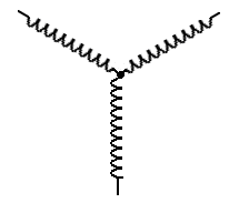
Notice that the three coils in the model alternator are connected together at one end. This is called a wye-winding because you can draw the configuration of the coils in a way that they form a shape that resembles the letter "Y".|
A wye motor or transformer winding |
With a wye winding the voltages all cancel at the central point where the coils are connected together. This becomes the zero-voltage reference and is called the neutral connection or neutral wire. The main advantage of the wye winding is the availability of the neutral connection.
Do not confuse the neutral connection with ground. The ground wire is connected to the earth and only carries current when something goes wrong. The neutral wire carries current in normal operation. Even though the neutral wire should be the same potential as an earth ground, wiring faults may cause it to have dangerous voltages. The neutral wire is often connected to the ground wire. It this case, a wiring fault will probably send current to ground and trip the circuit breaker. If the neutral wire is not connected to ground, such faults may not be detected, placing dangerous voltages on the neutral wire.
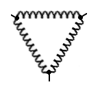
The other main type of transformer or motor winding is the delta winding. In a delta winding the three coils are connected in a triangle arrangement.
|
A delta motor or transformer winding |
The delta winding has no neutral connection so it is not used where a neutral connection is needed. The delta winding has the advantage of suppressing the third harmonic of the line frequency so it delivers a cleaner sine wave than the wye winding.
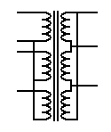
Power distribution transformers rarely have both the primary and secondary windings of the same configuration. Typically, at the power station transformers have wye windings connected to wye-wound alternators. The transformer secondary windings are delta-wound and feed current into the power grid over three wires.
|
A transformer with a wye primary (left) and a delta secondary |
When the voltage is stepped back down for the consumer, the transformer often has a delta-wound primary and a wye-wound secondary to create a neutral connection. However, there may also be a delta winding connected to the secondary to suppress the third harmonic and deliver a cleaner sine wave.
Voltage on the power grid
The voltage on each phase of the power grid varies from 110 volts to 240 volts depending on what country you are in. Most of the world uses 220 volts or 230 volts. We will be focusing on North American standards in this text because that is what the author is familiar with. The national standards for the United States and Canada are to have between 114 and 126 volts on each of the three phases compared to the neutral wire. The typical voltage is 120 volts although 117 volts is used in many cities.[2]With 120 volts per phase, the voltage between any two phases will be 208 volts. The reason the voltages don't add up to 240 volts is because the voltages are 120 degrees out-of-phase with each other; the voltages don't reach peak (maximum) at the same time. Mathematically, considering all voltages and phase angles, the voltages on all three wires add up to 240 volts.208-volt two-phase power
Wiring to residences and small businesses are delivered in one of two methods. First let's look at 208-volt two-phase powerMost texts say that connecting to two 120 phases gives you 240 volts. To avoid confusion we will use the same convention here.
Single-phase power
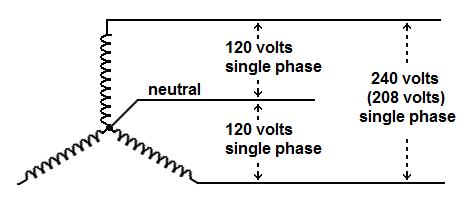
Three-phase power at 240 volts is delivered to industrial areas to drive industrial motors. Residential buildings and the office buildings need single-phase power at 120 volts. Some appliances require single-phase power at 240 volts. Single phase power at 240 volts is simply taken from two of the three phase wires (the actual voltage is 208 volts). One reason that wye windings are used on the consumer side of step-down transformers is the availability of the neutral connection. Connecting to one 120 volt phase and to the neutral wire gives you a 120 volt single-phase connection.|
240
volts single phase and 120 volts single phase taken from a wye winding. |
Question:
When you connect to two of the 120 volt phases, why isn't it called two phase power?
Compared to the neutral wire you
do
get
two phases. If you connect them to a dual trace oscilloscope, each
channel referenced to the neutral you will see two sine waves that are
120 degrees out of phase with each other. However, you don't use the
neutral wire when you make a 240
volt connection. Without the neutral wire we can only compare one phase
to the other phase. The phases combine into a single sine wave at 208
volts.
Therefore you have "240 volts" single phase.
Circuit breakers connect to the incoming power and deliver it to several circuits in the building. Circuit breakers for 120 volt circuits will connect to only one of the 120 volt phases. To balance usage, half of the circuit breakers are connected to one of the 120 volt phases and the other half will connect to the other 120 volt phase. The wire that is connected through the circuit breaker to a phase is now called a "hot" wire. In the U.S this wire is black.
"
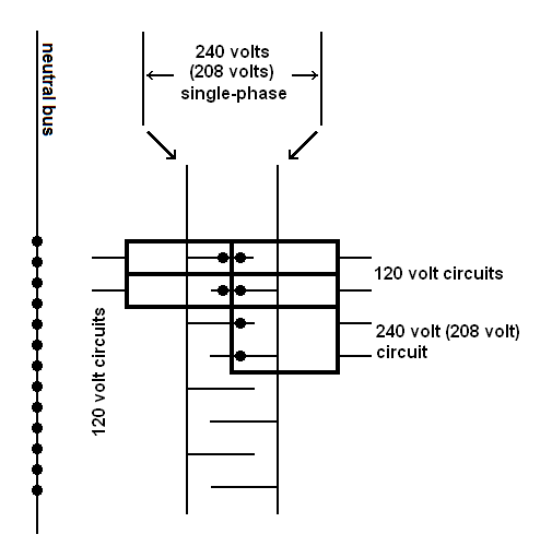
| One style of breaker box. Three metal bars called busses carry the power. 120 volt circuit breakers connect to the neutral bus and one of the 120 volt phases. 240 volt circuit breakers connect to both phases, but not the neutral. Each breaker has two outgoing wires. 120 volt breakers have a hot and a neutral wire. 240 volt breakers have two hot wires. |
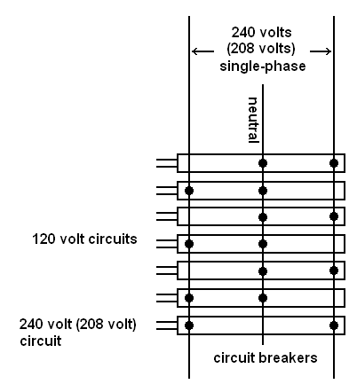
| Another style of breaker box. The neutral bus is separate from the phase buses. 120 volt circuit breakers connect to one phase. 240 volt circuit breakers are twice the width and connect to both phases. 120 volt breakers have one hot wire each. This hot wire is paired with another wire coming from the neutral bus. 240 breakes have two hot wires. |
With the circuit breaker box design shown in the left diagram above, the design of the circuit breaker determines which of the two 120 volt phases will be connected to the breaker. Both types of circuit breaker connect to the neutral wire. An electrician would have to be sure to balance the types of breakers used to balance the load. Such a breaker box will usually have one column of breakers. Each circuit breaker has a "hot" and a neutral wire in this type of box. For a 240 volt circuit a special circuit breaker is used that connects to both phases and not to the neutral bus. Another type of breaker box uses smaller breakers in two columns. In this case the circuit breakers are identical to each other but the electrician would equally fill each column. If a 240 volt circuit is needed a special 240 volt circuit breaker is used that connects to both 120 volt phases. Connecting to both 120 volt phases provides a 240 volt circuit. In modern wiring there is also a block connected to a true-earth ground with at least one ground wire fore each circuit. Each circuit will be connected to a number of light switches and wall sockets. You will find that approximately half of you light switches and wall sockets are connected to one phase and the other half to the other phase.
A typical 120 volt circuit handles 15 amperes and a 240 volt circuit handles 30 amperes. High-power appliances that need a 240 supply. Remember that power is the product of voltage and current. If you double the voltage and current, you quadruple the power. Some newer installations, particularly in office areas, have 20 ampere circuits. 20 ampere circuits can be identified by the wall plug, where the long contact (the neutral contact) it "T"-shaped.
The wall socket
In the United States and Canada, the wall socket has three connectors. Two of the connectors are rectangular and one is round. One of the rectangular conductors is longer than the other. The short connector, the hot connector carries the 120 volts from system. This is connected to the black wire. The long connector is the neutral connector and is connected to the white wire. A 20 ampere socket will have a "T"-shaped neutral connector. The round connector is the ground. This is a true-earth ground and comes from the green wire. The neutral connector and the ground connector should both have the same electrical potential, that is, zero volts.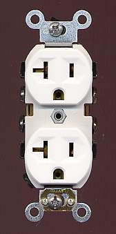
|
A 20 amp wall socket as found in the U.S. |
Consumer Generated Solar Power
Consumer generated solar power is becoming a major source of electrical energy. The solar panels on the owner's roof produce DC which must be converted to AC for consumption. The inverters used for this task are more sophisticated than the ones you can buy at Wal Mart for your car. They must synchronize to the power grid if the consumer wants to get power from the local electric utility when his own capacity runs short (long nights, high demand, etc.). In some systems, when the solar panels are producing more electricity than is being consumed extra power is distributed onto the power grid. When less power is being created than consumed power is taken from the power grid. Other systems use excess power to charge batteries for use when demand is greater than the solar panels can produce (e.g. night).AC Power Transmission and Distribution
Why Electricity is Distributed in Three Phases
Why Use Three Phases Follow-up
Answers to Questions - Voltage, Current and Safety
Modern Marvels - High Voltage
—————————
| Vocademy |