| Vocademy |
Variable resistors and potentiometers
Variable resistors are constructed with a resistive track (usually a
carbon film) that is contacted by a wiper. There is typically a
connection at each end of the resistive track and another to the wiper.
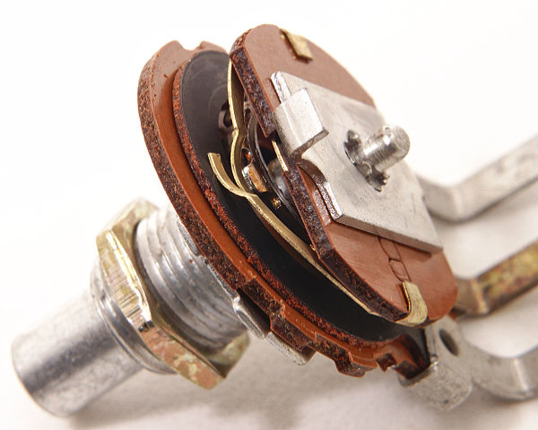
| A variable resistor showing the resistive track and the wiper. |
When there are three such connections, the device is called a
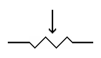
potentiometer or “pot” for short. The schematic symbol is based on this
construction. It is a resistor with an arrow pointing at it. This arrow
represents the wiper that can move anywhere along the resistor.
| +10 V to +20 V |
+10 V
|
 |
+20 V |
| A potentiometer can pick off any voltage between the ends of the device. |
The potentiometer can be placed in a circuit, connected by the
terminals at the ends of the resistive track, like any other resistor.
As such, compared to ground there will be some voltage at one end and
another voltage at the other, depending on the value of the pot and the
current flowing through it. Connected in this arrangement the wiper can
be moved along the resistive track and, depending on where it is on the
track it will have some voltage that is between the voltages at the
ends of the track.
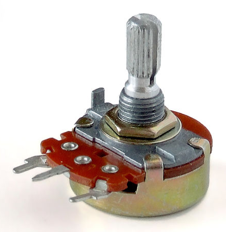 Panel Mount Potentiometer |
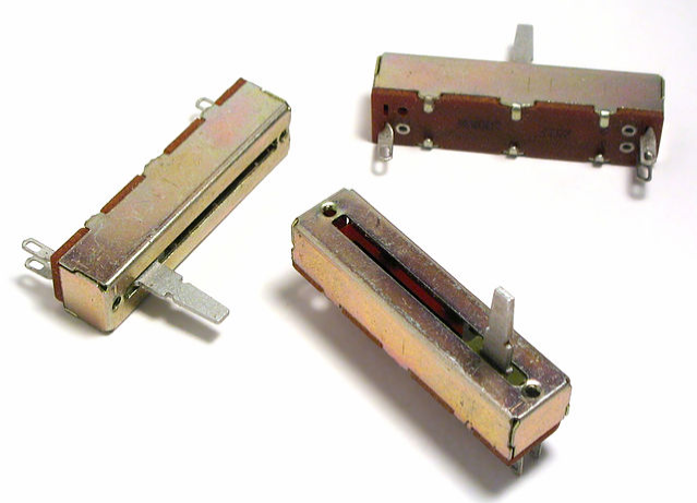 Slide Pots[1] |
 Trimpots |
|
Potentiometers
|
||
  Variable Resistor |
 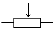 Potentiometer |
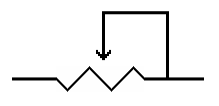  Potentiometer as a Variable Resistor |
| Schematic Symbols for Variable Resistors and Potentiometers |
||
When using a potentiometer as a variable resistor, you could simply
connect to one end of the resistive track and to the wiper. However,
the proper way is to connect the wiper to one end of the resistive
track as shown in the schematic symbols above. This assures that if
there is a fault, such as a burned spot on the resistive track, that
you will not have a point where the resistance becomes infinite. Such
an open circuit could be undesirable. The maximum resistance in case
the wiper loses its connection with the track will be the value of the
potentiometer.
Variable resistors are sometimes called rheostats. This term is becoming obsolete but is still widely used to refer to a high power wire wound variable resistor or potentiometer. A trimpot is a small potentiometer designed to be set with a screwdriver or trimpot adjusting tool.[2] They are not intended to be changed once the circuit is adjusted.
Variable resistors are sometimes called rheostats. This term is becoming obsolete but is still widely used to refer to a high power wire wound variable resistor or potentiometer. A trimpot is a small potentiometer designed to be set with a screwdriver or trimpot adjusting tool.[2] They are not intended to be changed once the circuit is adjusted.
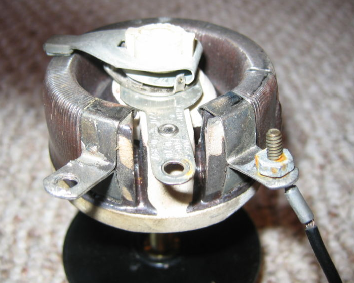
| A
large high power wire-wound potentiometer. The term “rheostat” is often
used to differentiate between smaller carbon track potentiometers and
these high power devices. |
Taper
The taper of a potentiometer refers
to how the resistance varies as the potentiometer is turned. A linear
taper pot varies equally for the same amount of turn. For example, if
you turn a 20k pot 1/4 turn, you will get a change of 5k. Another
1/4 turn
will change it by another 5k. A logarithmic or audio taper
potentiometer at 1/4 turn will have 2.5k of resistance. The next
1/4 turn
will increase to 5k. The following will increase to 10k and the last
1/4 turn
will take you to 20k. Notice that each 1/4 turn doubles the resistance. A
logarithmic or audio taper potentiometer is used in audio systems
because our ears hear on a logarithmic scale. Therefore, the changes in
level sound natural.
Potentiometers with Series and Parallel Circuits - Answers to Questions
—————————Potentiometers with Series and Parallel Circuits - Answers to Questions
| Vocademy |