| Vocademy |
Series-Parallel Circuits
As circuits become more complex, you will have resistors (or other
components) that are in a combination of series and parallel
configurations. Reducing such a circuit to a total resistance is not
something you will often need to do in the field. However, it is common
to have circuits that combine both series and parallel sections. It is
often important to follow where circuits branch to follow dividing
current paths. The key is to follow where the current paths split. When
two components are connected, but there is one current path, the
components are in series. If there is a split to two or more current
paths, the components are in parallel.
 |
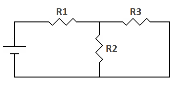 |
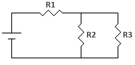
| Combination series-parallel circuits |
In the first circuit above, the positive terminal of the battery is
connected to R1 and nowhere else. There is only one current path at
that point. On the other side of R1 the circuit splits into two current
paths, one through R2 and the other through R3. Since there are now two
current paths we have a parallel circuit; R2 and R3. They are in
parallel with each other, but, together, they are in series with R1.
The second circuit above is electrically the same as the first. A
circuit is not a series or parallel circuit because of the way the
schematic is drawn but because of the way the components are connected.
In the second circuit, R3 is still connected in parallel with R2. In
either circuit, the current path splits where R1 meets R2 and R3, then
recombines where the opposite ends of R2 and R3 are connected together.
 |
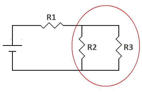 |
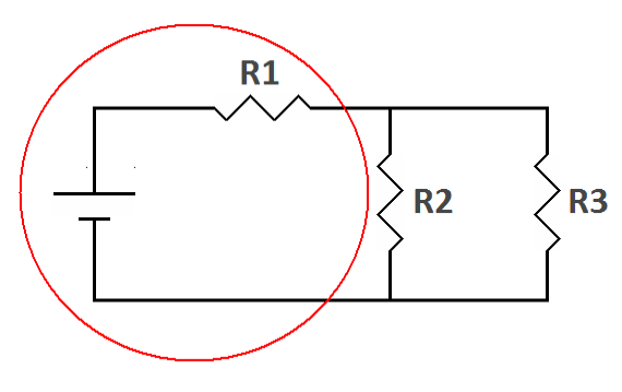
| The left part of the circuit is a series circuit (one current path) | The right part of the circuit is a parallel circuit (multiple current paths) |
In the next circuit you can see how the rules for series and parallel
circuits combine in a series-parallel circuit.
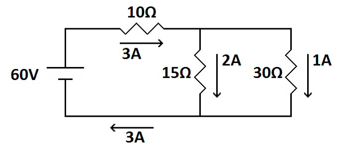
| The currents through the legs of the parallel part of the circuit add up to the current through the series part of the circuit. |
First, look at the current. Like a series circuit, the 3 amps flow
around the entire circuit. However, where the path splits, 2 of the 3
amps go through the 15 ohm resistor and the remaining 1 amp goes
through the 30 ohm resistor (greater current through the lesser
resistor). The current recombines where these two resistors are
connected together for the original total of 3 amps. This satisfies
Kirchhoff's Current Law. Next, look at the voltages.
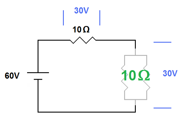
| The 15 ohm and 30 ohm resistors are in parallel with each other and total 10 ohms. Together they are in series with the 10 ohm resistor. If we take a “zoomed out” view the circuit acts like two 10 ohm resistors in series. Thus we see Kirchhoff's voltage law in effect where the 30 volts across the two parallel resistors adds to the 30 volts across the 10W resistor, totaling 60 volts. |
The battery supplies 60 volts. Half of this is lost across the 10 ohm
resistor (10 ohms x 3 amps = 30 volts). The other 30 volts are lost
across the combination of the 15 ohm and 30 ohm resistors in parallel.
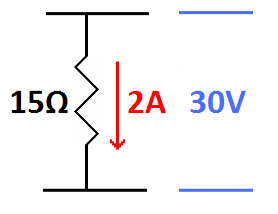
You can demonstrate this through each individual resistor (15 ohms x 2
amps = 30 volts or 30 ohms x 1 amp = 30 volts)
 |
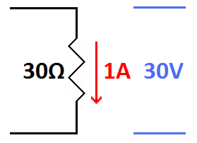 |
| Either of the two resistors in parallel yields the same voltage after applying Ohm's law. |
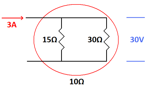
You can also demonstrate this through both resistors as a whole (30
ohms in parallel with 15 ohms = 10 ohms, 10 ohms multiplied by 3 amps =
30 volts).
 |
 |
| The two resistors in parallel act as a single 10 ohm resistor. Applying Ohm's law we still get the same voltage. |
Be careful, don't forget your parallel circuit rules. Do not add the 30
volts across the 15 ohm resistor to the 30 volts across the 30 ohm
resistor to get 60 volts.
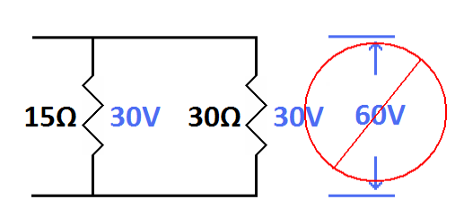
| The two voltages across the resistors in parallel do not add together. The single instance of voltage is across both resistors. |
It is the same 30 volts across both resistors in combination. 30 volts
is lost across the 10 ohm resistor then another 30 volts is lost across
the combination of the 15 ohm and 30 ohm resistors in parallel. This
equals the 60 volts supplied by the battery and satisfies Kirchhoff's
Voltage Law.
Also, don't make the common mistake of placing the battery voltage of 60 volts across the 10 ohm resistor. They are in series with each other and the voltages will be different.
Also, don't make the common mistake of placing the battery voltage of 60 volts across the 10 ohm resistor. They are in series with each other and the voltages will be different.
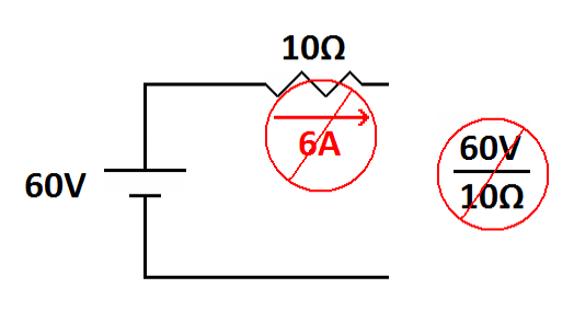
| Do not apply the battery voltage to the adjacent resistor. Only part of the battery voltage applies to this resistor. |
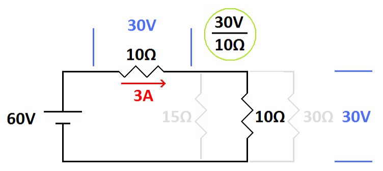
Be sure you don't apply the voltage at one part of a series circuit to
another part of the circuit (series circuit rule: the voltages are
different).
|
This is correct
The 15 ohm and 30 ohm resistors are combined making a resistance of 10 ohms. Now the source voltage of 60 volts is equally divided between the equal resistors (10 ohms and 10 ohms) in series. Now you can correctly calculate the current. Use either 30 volts across one of the 10 ohm resistors as shown or 60 volts across both resistors (20 ohms). Either way you get 3 amperes. |
Exercise:1
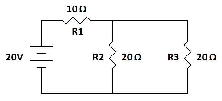
| What is the
combined resistance of R2 and R3? __________ What is the total resistance of the circuit? __________ What is the voltage across R1? _________ What is the voltage across R2? _________ What is the current through R2? _________ What is the current through R3? _________ What is the current through R1? _________ |
| 1 | • |
R2 and R3 together are 10 ohms. |
| • |
The total resistance is 20 ohms. The whole circuit acts like two 10 ohm resistors in series. | |
| • |
Two equal resistors in series will share half the total voltage each. R1, therefore has 10 volts across it as do R2 and R3. | |
| • |
R2 and R3. each have 0.5 amps. | |
| • | The combined current, which goes
through R1 is 1 ampere. |
Series-parallel circuits
Series-parallel circuits
Series-parallel circuits
| Vocademy |