| Vocademy |
Tunnel diode

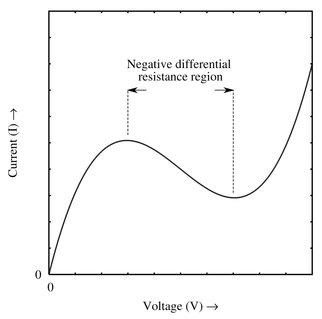
A tunnel diode has characteristics different from other diodes. When reverse biased it has a linear voltage-to-current curve. In other words, it looks much like a resistor when reverse biased; double the voltage and you double the current. When forward biased a tunnel diode also looks like a resistor at low voltages. Once a certain voltage is reached, further increasing the voltage causes a decrease in current. This is the opposite of practically any other device, where an increase in voltage causes an increase in current. The range of voltage where this occurs is called the "negative resistance" region. When the voltage approaches the threshold voltage (0.3 volts for germanium and 0.7 volts for silicon) it begins to act like a normal forward-biased diode.
 |
|
|
The characteristics of a tunnel diode are caused by quantum tunneling. This phenomenon is where charge carriers with insufficient energy to cross the depletion region nevertheless cross the region, causing significant conduction where ordinary diodes will conduct little. This quantum tunneling occurs when reverse-biased and at low voltages when forward-biased. When quantum tunneling occurs, the diode acts like a resistor with a linear voltage-to-current relationship. When the forward-biased voltage reaches the Peak Point Voltage (around 50 to 100 millivolts for a germanium tunnel diode), the quantum tunneling starts to decrease. The result is that the current decreases linearly as voltage increases. This continues until the Valley Point Voltage is reached (around 300mV for a germanium tunnel diode), after which the tunnel diode follows the characteristics of a typical germanium diode. The tunnel diode can be thought of as a voltage-sensitive variable resistor. When reverse-biased and below the Peak Point Voltage when forward-biased, it has a low resistance of around five to ten ohms. After passing the Peak Point Voltage, the resistance increases exponentially, which causes the current to decrease linearly as the voltage increases. This is the so-called negative resistance region. This continues until the Valley Point Voltage is reached, where the resistance decreases such that the current increases exponentially as with a typical diode.
LGM model
Like the zener diode you can imagine a tunnel diode using the Little Green Man model. In the case of the tunnel diode, the diode is forward biased and the little green man has a chart of the tunnel tiode charastic curve. His job is to make the resistance of the diode whatever it takes to cause to current to match the cureve at the specified voltages.
Uses
Tunnel diodes are often used as the active component of very high-frequency oscillators. Consider a circuit consisting of a tunnel diode in series with a tank circuit. When the tank circuit is caused to oscillate, Following Kirchhoff's Voltage Law, the voltage across the tunnel diode will drop as the voltage across the tank circuit rises, and vice versa; the voltage across the tunnel diode will be 180 degrees out of phase with the voltage across the tank circuit. If the tunnel diode is biased correctly, it will be put into its highest current state (the Peak Point Voltage) when the tank circuit is in its highest voltage state. This will push current into the tank circuit, forcing the voltage even higher, thus compensating for losses, and keeping the tank circuit oscillating. When the tank circuit is in its lowest voltage state, the tunnel diode will be in its lowest current state (at the Valley Point Voltage), allowing the tank circuit voltage to drop, thus not putting current into the tank circuit at the wrong time. Think of it like a little green man controlling a variable resistor in series with the tank circuit. He controls the resistance to feed current into the tank circuit at just the right time to compensate for losses.
| Vocademy |