| Vocademy |
Solutions to the puzzlers:
To increase the collector current without saturating the transistor, us
a lower value collector resistor. The circuit becomes saturated when
the voltage across the collector resistor is approaching the battery
voltage. If you have less resistance for the collector resistor it will
have less voltage across it for the same current as a higher value
resistor. The lower value resistor will take more current before its
voltage approaches the battery voltage. The disadvantage of a
lower-value collector resistor is it reduces the voltage gain of the
amplifier.
Now for the gate resistor in the common-source amplifier.
Now for the gate resistor in the common-source amplifier.

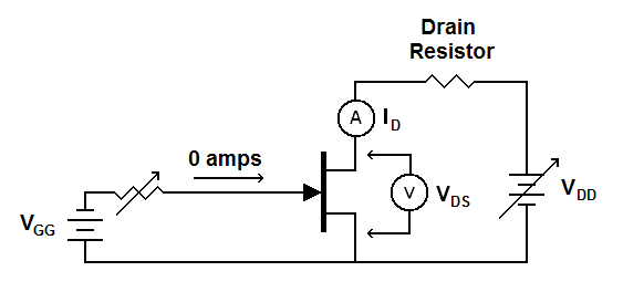
The above circuit has no gate
resistor. Recall that little or no
current flows into or out of the gate of an FET. With no current
flowing through the variable resistor there can be no voltage drop
across it. The voltage on the right side of the variable resistor will
be the same as the voltage on the left side. The gate voltage will be
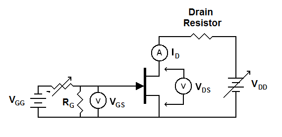
the battery voltage (VGG) regardless of the setting of the variable resistor. Now look at the test circuit from Transistor Characteristics.

Here the gate resistor (RG) forms a current path so current
can flow through the variable resistor. It also forms a voltage divider
with the variable resistor. Now, as you change the value of the
variable resistor the gate voltage will change.
Also an FET will consist of either two conductive materials separated by an insulating material (for MOS transistors) or will be a reverse-biased PN junction (for J-FETs). Either way you have two conductors separated by an insulator—a capacitor (reverse-biased junctions in Semiconductors). So, an FET not only acts as described in these discussions, but acts as if there were a capacitor between the gate terminal and the actual gate of the transistor. The following illustration shows what an FET looks like to the rest of the circuit. The capacitor is actually part of the transistor but the circuit acts the same as if there were a capacitor in series with the gate.

In addition, these test circuits have a battery supplying the gate voltage. The output impedance of a battery is very low and will discharge the gate. In fact, we just discussed that without the gate resistor the gate voltage will equal the battery voltage. A real-world circuit will not have this battery. It will be connected to the output of another circuit or device. If that circuit or device has a high output impedance this "parasitic" capacitor will not be able to discharge when the driving circuit's voltage drops. (see Interaction of Output Impedance and Input Impedance and Capacitors in DC Circuits). As a result the FET gate will charge up to the highest DC voltage applied to it and sit there. The gate resistor (RG) provides a current path to discharge the gate allowing the voltage to change. You will see this resistor in circuits where the output of a high impedance device or circuit is coupled to an FET.
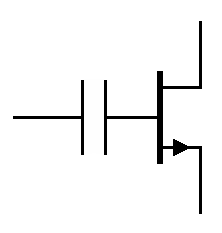
Also an FET will consist of either two conductive materials separated by an insulating material (for MOS transistors) or will be a reverse-biased PN junction (for J-FETs). Either way you have two conductors separated by an insulator—a capacitor (reverse-biased junctions in Semiconductors). So, an FET not only acts as described in these discussions, but acts as if there were a capacitor between the gate terminal and the actual gate of the transistor. The following illustration shows what an FET looks like to the rest of the circuit. The capacitor is actually part of the transistor but the circuit acts the same as if there were a capacitor in series with the gate.

| An FET looks like a transistor with a capacitor in series with the gate. |
In addition, these test circuits have a battery supplying the gate voltage. The output impedance of a battery is very low and will discharge the gate. In fact, we just discussed that without the gate resistor the gate voltage will equal the battery voltage. A real-world circuit will not have this battery. It will be connected to the output of another circuit or device. If that circuit or device has a high output impedance this "parasitic" capacitor will not be able to discharge when the driving circuit's voltage drops. (see Interaction of Output Impedance and Input Impedance and Capacitors in DC Circuits). As a result the FET gate will charge up to the highest DC voltage applied to it and sit there. The gate resistor (RG) provides a current path to discharge the gate allowing the voltage to change. You will see this resistor in circuits where the output of a high impedance device or circuit is coupled to an FET.
Transistor Summary
- A transistor is like a pneumatic relay valve.
- A transistor acts like an electrically-controlled variable resistor.
- The terminals of a bi-polar junction transistor (BJT) are called the collector, emitter and base.
- For an NPN transistor conventional current enters the collector and exits the emitter. The base controls the current.
- A BJT is current controlled. A small base current causes a much larger collector current.
- The gain of a BJT is called hFE
- hFE is the ratio of collector current to base current.
- The terminals of a field effect transistor (FET) are called the drain, source and gate.
- For an N-channel FET conventional current enters the drain and exits the source.
- An FET is voltage controlled. Changing the gate voltage changes the drain current.
- A MOS transistor or MOSFET is named for the layers of Metal, Oxide and Semiconductor.
- MOS transistors can be damaged static electricity.
| Vocademy |