| Vocademy |
Integrated Circuits
Modern solid state devices are made
on wafers of silicon using a process called photolithography. The
process is explained in the videos accompanying this discussion. An
integrated circuit (IC) is made by the same process. When making
individual (discreet) devices, many devices are made on a wafer of
silicon. Then they are cut apart and packaged separately. An IC is made
by making many interconnected devices on the silicon waver. Then whole
circuits are cut apart an packaged. Early ICs had a few transistors and
diodes making up simple circuits. Today, some ICs have over one billion
transistors on a single silicon "chip".
One problem with integrated circuits is inductors and capacitors. Only tiny amounts of inductance and capacitance can be squeezed into the space available on a silicon chip. If an IC needs large value inductors and capacitors they must be discreet devices external to the IC. Many analog ICs also require external resistors to complete the circuit's functionality.
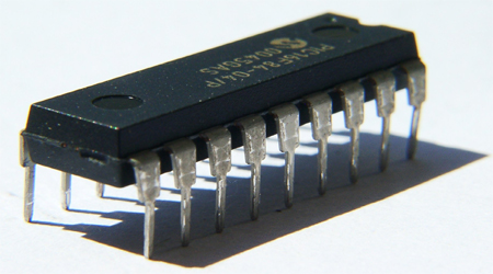
Integrated circuits are packaged in many ways. One of the most popular packages is the Dual-Inline Package or DIP.

|
|
 | |
 |
| Dual Inline Package (DIP) |
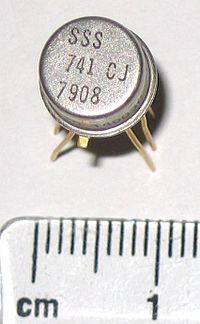
TO-5 |
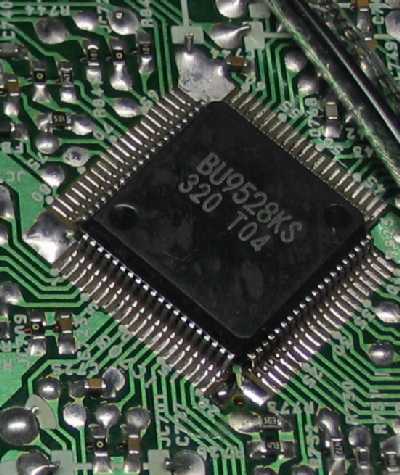
Surface Mount |
| Integrated Circuit Packages |
A DIP package is
rectangular in shape and has two rows of pins on opposite sides of the
package. The pins are spaced 1/10 or an inch apart with the rows
usually 3/10 of an inch apart. Another popular package for small ICs is
the TO-5 package. This is the same size and shape as the TO-5
transistor package but with (usually) 8 pins. A popular package for mass production is the surface mount package.
Pinouts
 |
 |
| DIP |
TO-5 |
The numbering of the pins, called the pinout, is read counter-clockwise
looking from the top. Pin one is indicated by a tab on TO-5 packages
and by a dot, a notch or both on DIP packages.
Types
There are two main types of ICs. Analog ICs come in a wide variety of
circuits. Operational Amplifiers, voltage regulators, oscillators and
FM stereo decoders are just a tiny example. Digital ICs can be anything
from a small package of logic inverters to multi-core processors for
computers. It is often said that digital circuits use 1s and 0s (ones
and zeros). However, digital circuits usually have two possible
voltages. People use the numbers 1 and 0 to represent these voltages.
The actual voltages depend on the circuit.
Digital ICs come in several logic families but the most common are TTL and CMOS.
Digital ICs come in several logic families but the most common are TTL and CMOS.
TTL
TTL (Transistor-Transistor Logic) integrated circuits are made using
bi-polar junction transistors. The logic gates in TTL circuits are
often characterized by multiple emitters on a single transistor. TTL
circuits have the advantage of speed at a sacrifice of power
efficiency. Most TTL circuits have a part number that starts with 74
for commercial grade circuits and 54 for military grade. For example,
the 7404 contains six TTL logic inverters.
TTL logic levels
TTL circuits always operate from 5-volt power supplies. The two
possible states are 5 volts and 0 volts. Using the 1 and 0 model, 5
volts represents a logical 1 or a logical high and 0 volts represents a
logical 0 or logical low.
CMOS
CMOS (Complementary Metal-Oxide-Semiconductor) integrated circuits are
made using MOS field-effect transistors. Each gate is made from
complementary pairs of transistors.

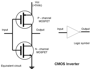
| A simple CMOS inverter. To the left is the schematic, to the right is the logic symbol. |
For example, a CMOS logic inverter
uses one P-channel transistor and one N-channel transistor. They are
arranged so that a logical 1 turns off the top transistor (see the
diagram above) and turns on the bottom transistor thus connecting the
output to ground. A logical 0 turns on and
off the opposite transistors thus connecting the output to the supply
voltage (VCC). CMOS circuits have the advantage of very low power consumption
but are much slower than TTL circuits. However, recent improvements
have greatly increased the speed of CMOS circuits. Most CMOS circuits
have part numbers that begin with 40. For example, the 4049 contains
six inverter/buffer circuits. Some CMOS circuits are designed to be
pin-for-pin replacements for TTL circuits. These circuits usually have
part numbers that start with 74C. For example, the 74C04 is a
pin-for-pin replacement for the 7404 TTL circuit.
Like MOSFETs, CMOS circuits are very sensitive to electrostatic discharge.
Since CMOS circuits have high impedance outputs, a CMOS circuit cannot drive a TTL circuit. In other words, you cannot connect the output of a CMOS circuit to the input of a TTL circuit (see impedance matching in DC Circuits). Likewise, CMOS circuits cannot drive other low impedance circuits and devices, such as LEDs. The 4049 and the 4050 are special CMOS circuits that are designed to drive low impedance circuits. If you need to drive LEDs or TTL circuits from a CMOS circuit, the 4049 or 4050 can be used as a go-between.
CMOS Logic levels
CMOS circuits typically operate from power supplies ranging from 3 to
12 volts. A logical 0 would be 0 volts and a logical 1 would be the
power supply voltage. For example, if the circuit is operating from a 9
volt power supply, 0 volts would be a logical 0 and 9 volts would be a
logical 1. If a CMOS circuit is driving a TTL circuit (via a 4049 or
4050), all of the circuits must be run from 5 volts.
Using Integrated Circuits
Some IC packages, such as surface
mount packages, require specialized soldering and desoldering
techniques. This discussion is for another time. Otherwise, a
transistor is a transistor and a diode is a diode. Being in a
monolithic package doesn't change how the devices work. Using IC is
about knowing what package pin connects to what part of the circuit
then designing or troubleshooting accordingly. This is shown in the
datasheet for each circuit. When an IC fails it will typically exhibit
an open circuit or short circuit condition at one or more pins. There
is no way to repair the circuit. It must be removed and replaced.
We will work with some integrated circuits in Analog Circuits and Digital Circuits.
We will work with some integrated circuits in Analog Circuits and Digital Circuits.
Z2 - Upgraded Homemade Silicon Chips
Uncovering the Silicon: Demystifying How Chips are Built...
| Vocademy |