| Vocademy |
Transistors
Before talking about transistors, let's talk about trucks and air brakes (stay with me here, believe it or not it's relevant). Air brakes work by sending compressed air into a closed cylinder that contains a piston. The compressed air pushes this piston that in turn pushes a crank that rotates a shaft.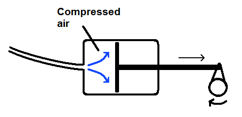
| Air
brakes operate by sending compressed air against a piston in a brake
chamber. This pushes a crank that rotates a shaft. |
This rotating shaft turns a cam that pushes the brake shoes against the brake drum.
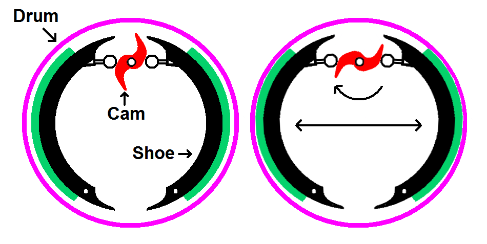
| The rotating shaft rotates a
cam. When the cam rotates it pushes the brake shoes against the brake
drum. |
What does this have to do with electronics? Recall from Capacitors in DC Circuits that a capacitor acts like an air tank. The brake chamber is an air tank with a piston inside. To push the piston you must fill the chamber with compressed air. This is just like charging a capacitor with electricity.
The air hose leading to the brake chamber acts like a wire. Just as a wire has some electrical resistance an air hose has some resistance to the flow of compressed air. The air brake system has a form of resistance and capacitance and has a time constant just as an RC circuit does. If the air hose has more air resistance (e.g. it is thinner, longer or both) it takes longer to fill the brake chamber.
Now that we have established that an air brake circuit is like an RC electrical circuit, let's take a look at a slight problem with the air brakes of a large truck. Each axle has two brakes and each brake has a brake chamber.

| When the driver presses the
brake pedal it sends compressed air to the brake chambers through the
brake hoses (red). |
The brakes at the front of the truck have relatively short hoses leading to them. However, the brakes at the rear of the trailer have a long hose leading to them. Just as a long wire has more electrical resistance than a short wire, a long hose has more air resistance than a short hose. This is like adding more resistance to an RC circuit. It takes longer for the brake chambers at the rear of the trailer to fill with compressed air than those at the front of the truck. When the brakes are applied the tractor brakes will lock up before the trailer brakes begin to work. The steering wheels will skid while the trailer wheels still have traction. This is called a front wheel skid. Truck drivers are a bit superstitious and consider a front wheel skid bad luck (for more information see Jackknifing on Wikipedia).
To solve the problem there is a secondary air tank at the rear of the trailer. This tank is always filled with compressed air when the truck is rolling (it is empty when the parking brake is set). This tank is connected to a relay valve.
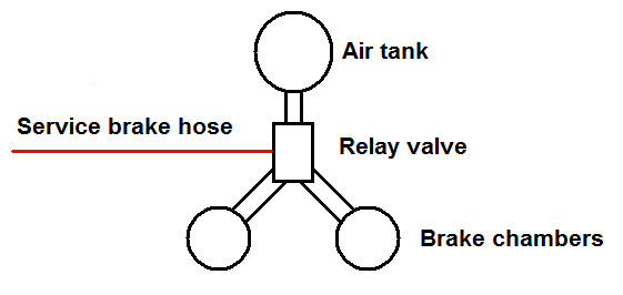
| When a truck is rolling
compressed air fills a tank at the rear of the trailer. This puts a
source of compressed air near the trailer brake chambers. |
When the brake pedal is pressed air from the air hose is applied to the relay valve.
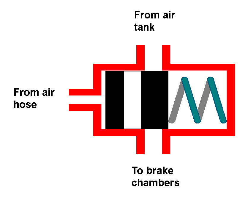 |
| Relay
valve closed. While the truck is
rolling the relay valve blocks the air path from the secondary tank to
the brake chambers.
|
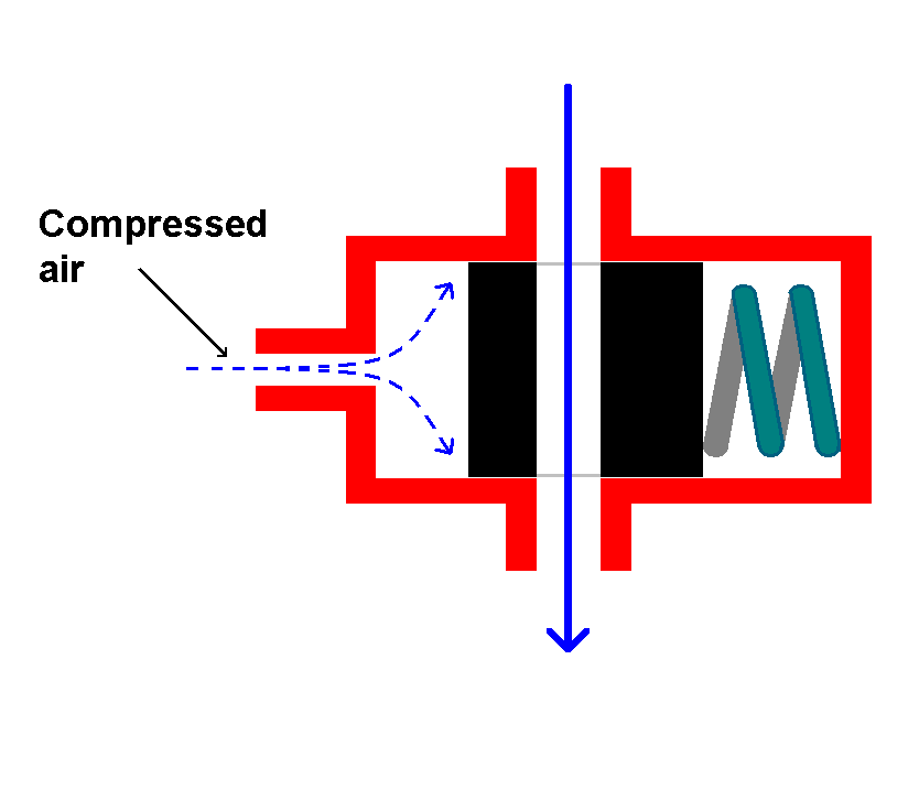 |
| Relay valve open. When the brakes are
applied a tiny amount of compressed air enters the valve body and opens
the valve.
|
The relay valve takes only a tiny amount of air to operate and opens quickly when the brakes are applied. It then sends a large amount of air from the secondary air tank directly to the brake chambers.
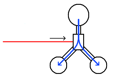
| When the relay valve opens a
large amount of compressed air goes
directly into the trailer brake chambers. There is now no significant
delay
between the tractor brakes and the trailer brakes. |
What does this have to do with transistors? The relay valve is like a mechanical transistor. It does the same thing with compressed air that a transistor does with electricity (except there are no moving parts in a transistor). A relay valve is a pneumatically operated valve. A transistor is an electrically operated switch or variable resistor.
A transistor as a voltage-controlled variable resistor
Remember the LGM model for the zener diode (see Diodes). We can use a similar LGM model to visualize how a transistor works. In this model we have an input voltage that is monitored by a little green man. His job is to adjust a variable resistor to control the current through the transistor.
| The LGM model for a generic
transistor. |
The little green man watches the input voltage and the output current. He adjusts the variable resistor to whatever resistance it takes to set the output current to a value based on the input voltage. Some transistors cause the current to go up as the input voltage goes increases and others do the opposite. Some cause the current to change in relation to input current rather than input voltage. In any case, we have a device that changes its resistance to whatever it takes to keep the current at some value based on an electrical input. This shows that a transistor acts much like an electrically-controlled variable resistor. The term "transistor" is a combination of the words "transfer" and "resistor". It transfers electrical signals from the input to the output (like an electrical version of the relay valve).
A Transistor in Action
The following video gives a quick demonstration of how a transistor works.Transistor Demonstration from 'The Secret Life of Machines'
Here is a schematic of the circuit shown in the video.
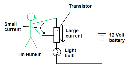
| Schematic for the circuit in the video |
The transistor in the video is a current-controlled type. The 12 volt battery is only able to push a few milliamps through the presenter's body. This current goes into the input of the transistor and causes it to conduct about an ampere of current through the light bulb.
Types of Transistors
There are two main types of transistors that work by different
mechanisms. First we will look at Field-Effect Transistors (FETs).
These use an electric field (static electricity) to control current
through a conducting channel. After that we will look at Bi-polar
Junction Transistors (BJTs). These use a small current through a
forward-biased junction to cause a larger current to flow through a
nearby reverse-biased junction.Transistor Basics
How a Transistor Works
Unijunction Transistor - Answers to Questions
| Vocademy |
